See all blog posts in this series:
- OpenShift Virtualization on IBM Cloud, part 1: Introduction
- OpenShift Virtualization on IBM Cloud, part 2: Becoming familiar with VPC
- OpenShift Virtualization on IBM Cloud, part 3: Deploying ROKS, ODF, and OCP Virt
- OpenShift Virtualization on IBM Cloud, part 4: Creating a virtual machine
- OpenShift Virtualization on IBM Cloud, part 5: Migrating a virtual machine
- OpenShift Virtualization on IBM Cloud, part 6: Backup and restore
- OpenShift Virtualization on IBM Cloud, part 7: Dynamic resource scheduling
In this post we will leverage the OpenShift APIs for Data Protection (ADP) using Velero and Kopia to backup and restore our virtual machines.
Installation
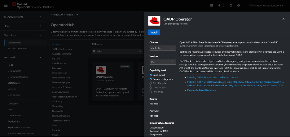
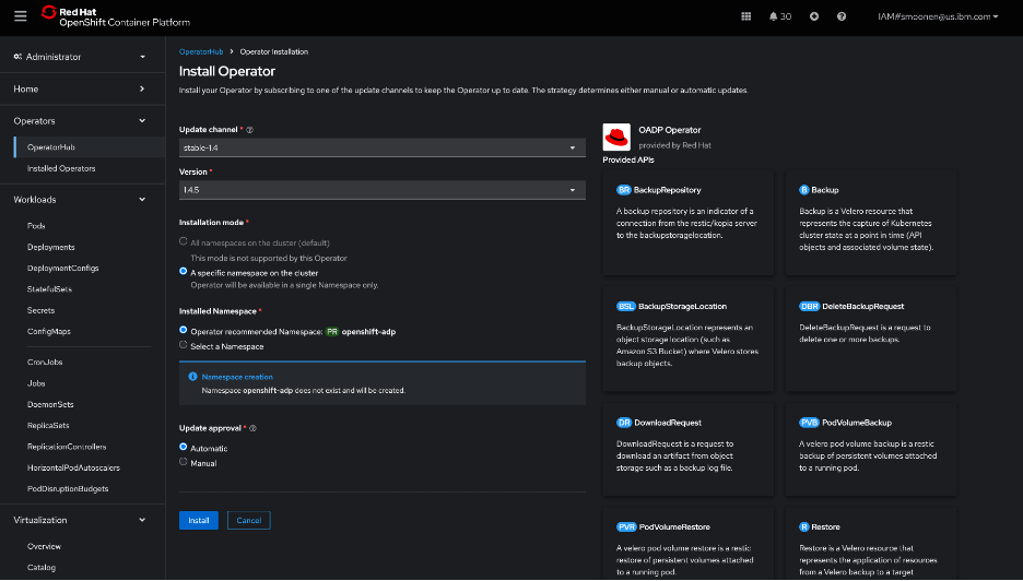
RedHat’s OpenShift APIs for Data Protection (OADP) leverages Velero to provide backup capabilities. In my OpenShift web console, I visited the OperatorHub and installed the RedHat OADP Operator.
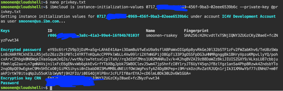
I then created an IBM Cloud Object Storage bucket. I created a service ID and created HMAC credentials for it. For reference:
Following the OADP instructions, I created a credentials-velero file holding the HMAC credentials and a default secret based on it.
I then created and applied a DataProtectionApplication YAML modeled from the OADP instructions and including my bucket details. Some noteworthy points:
- I used the VPC “direct” URL. Note that you need to prefix this URL with “https://”.
- Note also that I have added the “kubevirt” plugin as we will be needing this later.
- Kopia sems to be recommended as a preferred data mover for kubevirt over Restic. I have specified this below.
apiVersion: oadp.openshift.io/v1alpha1
kind: DataProtectionApplication
metadata:
  namespace: openshift-adp
  name: dpa-scotts-cos-bucket
spec:
  configuration:
    velero:
      defaultPlugins:
      - openshift
      - aws
      - csi
      - kubevirt
    nodeAgent:
      enable: true
      uploaderType: kopia
  backupLocations:
    - velero:
        provider: aws
        default: true
        objectStorage:
          bucket: smoonen-oadp-xy123d
          prefix: velero
        config:
          insecureSkipTLSVerify: 'true'
          profile: default
          region: us-south
          s3ForcePathStyle: 'true'
          s3Url: https://s3.direct.us-south.cloud-object-storage.appdomain.cloud
        credential:
          key: cloud
          name: cloud-credentials
I followed the steps to verify that this was deployed properly.

Next I created a schedule to run an hourly backup of the default namespace in which my new and migrated VM live. I could have chosen to provide a selector to backup specific VMs but for now I am not doing so. Notice that the defaultVolumesToFsBackup parameter is commented out; I had originally believed that this should be specified, but read on for some confirmation that this is not needed for ODF-backed virtual machines at least. Note also that this is a similar format to what is needed for a point in time backup, except that much of the configuration is here nested under template.
apiVersion: velero.io/v1
kind: Schedule
metadata:
  name: smoonen-hourly-backup
  namespace: openshift-adp
spec:
  schedule: 30 * * * *
  template:
    hooks: {}
    includedNamespaces:
    - default
    storageLocation: dpa-scotts-cos-bucket-1
    snapshotMoveData: true
    #defaultVolumesToFsBackup: true
    ttl: 720h0m0s
I found that my backup was “PartiallyFailed.”

Browsing the controller logs, it appears that there were failures related to pods not being in running state. This was the case for me because I had some prior migration attempts failing for various reasons such as lack of access to the VDDK image.
I then installed the Velero CLI to see what additional insight it would give me. It seems to automatically integrate with oc. It is able to provide some insights, but interestingly, it attempts to extract some data from IBM Cloud Object Storage which it is unable to do because I am attempting to access using the direct URL from outside of a VPC.

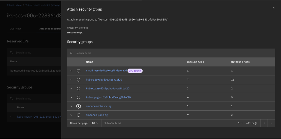
So I switched to running oc and velero on my VPC VSI jump server. When doing this, I discovered that the reason direct access to the COS storage was working for me at all was because ROKS had already automatically created a VPE in my VPC for COS direct access. I had to expand the security group for this VPE to allow my jump server to connect.
After doing so, the commands are now successful. Most of the errors and warnings were as I expected, but there were also warnings for block volumes for my two virtual machines that cause me to second-guess the use of FS backup as noted above.

Therefore I updated my schedule to remove the FS backup as noted above. This significantly reduced my errors. I also identified and cleaned up a leftover PVC from a failed migration attempt. Digging into the PVCs also led me to archive and delete my migration plan and migration pod in order to free up the PVC from the successful migration.

My next backup completed without error.

Kopia seems to be appropriately processing snapshots incrementally; or if not, it is doing an amazing job at deduplication and compression. For my two VMs, with a total storage of 55GB, my COS bucket storage increased by 0.1GB between two successful backups. Collecting a longer series of backups, the storage increase reported by COS seems to be around 0.17GB per increment.

I next attempted to restore one of these backups to a new namespace.
apiVersion: velero.io/v1
kind: Restore
metadata:
  name: test-restore
  namespace: openshift-adp
spec:
  backupName: smoonen-hourly-backup-20250924233017
  restorePVs: true
  namespaceMapping:
    default: test-restore-application
In this case the persistent volumes were restored, but the VMs were not re-created due to an apparent MAC address conflict with the existing VMs.

I learned that the following labels are commonly used when restoring virtual machines:
- velero.kubevirt.io/clear-mac-address=true
- velero.kubevirt.io/generate-new-firmware-uuid=true
I added the first to my restore definition.
apiVersion: velero.io/v1
kind: Restore
metadata:
  name: test-restore
  namespace: openshift-adp
  labels:
    velero.kubevirt.io/clear-mac-address: "true"
spec:
  backupName: smoonen-hourly-backup-20250924233017
  restorePVs: true
  namespaceMapping:
    default: test-restore-application2
This restore was successful.

The virtual machines are constituted in the new namespace.

Because this was a backup and restore of the entire namespace, even my ALB was reconstituted!

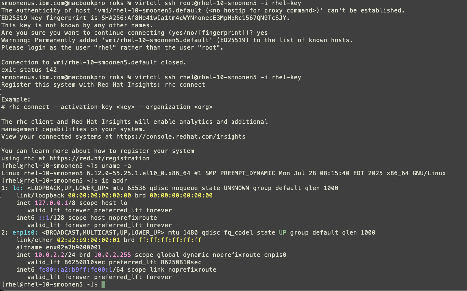
Thus I am able to SSH to that endpoint / VM.