If you consider the VPC object model, it is clear that to deploy and manage a large-scale environment, you need to consider the use of automation. Your operational challenge is further multiplied if you are planning for disaster recovery and intend to replicate or re-create your VPC environment from one region to another.
I’ve created a relatively simple set of Terraform modules with the goal of demonstrating how to:
Deploy a simple two-tier autoscaling application to one IBM Cloud region;
Create a skeleton VPC network topology for this application in a second IBM Cloud region, in preparation for disaster recovery;
Replicate application data from the first region to the second region; and
Failover the application to the second region in case of a disaster
Application design
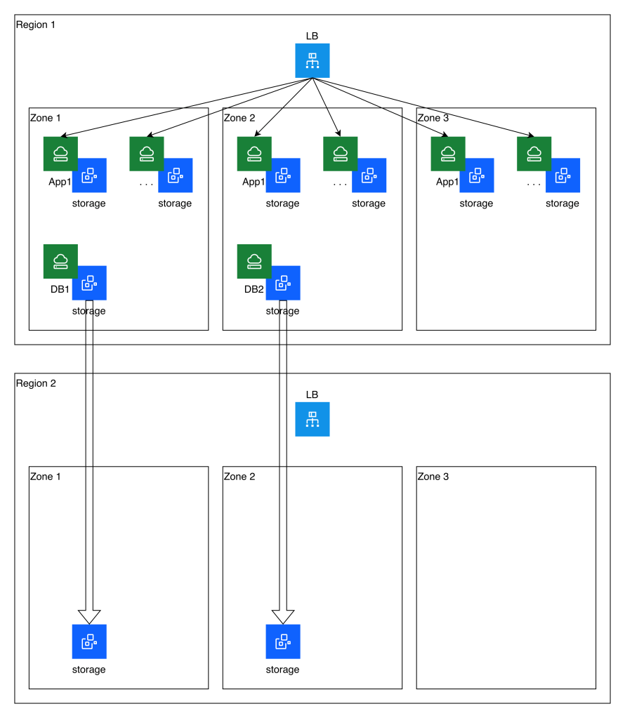
My two-tier application is a toy application. It consists of:
An IBM Cloud regional application load balancer; in front of
A set of three or more autoscaling application VSIs spread across the three zones of the region; connected to
A pair of primary-standby database VSIs spread across the first two zones of the region
The “application” running in the first tier is simply SSH. The VSIs share a common SSH host key much like you would share a certificate among a web application.
The database is PostgreSQL configured in streaming replication mode. The “application” connection to the database is simply by means of the psql command. The database is configured to allow direct connection from the application VSIs without password.
Failover within the primary region of the primary database server is beyond the scope of this test. You would need to develop your own automation or administrative process to manage the PostgreSQL failover and the DNS reassignment.
The following diagram illustrates the application topology as well as the storage replication that is established to a secondary region:
Replication
As we discussed previously, this automation leverages block storage snapshots and cross-region copies as a simple approach to replication. This imposes some limitations, including a lack of write-order consistency between volumes, and RPO constraints. This simple example has volumes that can be copied at hourly intervals, but a real-world example is likely to have a longer RPO.
Because of the lack of write-order consistency, in this model you would need to assess which of the two databases had won the race and should be reconstituted as the primary database server. If you were storing and replicating application data (for example, transaction logs stored on IBM Cloud VPC file storage which is also being replicated to the secondary region) you would need to perform a similar analysis of consistency before completing the recovery process.
In this example, since the application servers are stateless, their storage is not replicated to the secondary region. They can be re-created purely from their definition.
Failover
You can see from the diagram above that no running infrastructure other than the load balancer exists in the secondary region during steady-state replication. Upon failover, this example leverages an additional Terraform module to identify the most recent copied storage snapshot and re-create the instances and instance groups for the application and database servers.
In this article we will briefly consider the native capabilities of IBM Cloud VPC VSI that you could use to build a disaster recovery solution and compare this with alternative approaches.
Copied snapshots
As we saw previously, the IBM Cloud Backup for VPC backup policies allow you not only to schedule the creation of snapshots for your VSI volumes, but you can also schedule the copying of these snapshots to another IBM Cloud region. You could use this approach to perform periodic replication of all of your VSI data to another region for the purpose of disaster recovery. This approach has a number of limitations that you should take into consideration:
We saw that for in-region snapshots, you can create policies that will generate consistent snapshots of all of the volumes of individual VSIs, but not of multiple VSIs. By contrast, policy-based cross-region snapshot copies are available only if you snapshot volumes by tag without respect to their associated VSI. These snapshots and copies are not write-order consistent even within a single VSI. If you wanted to work around this limitation, you would need to use the API or CLI to invoke VSI-consistent snapshots and then separately invoke individual copies of each volume to another region.
You could combine such automation with automated quiesce activity in your VSIs if you wanted to ensure that you had stable replicas or even to possibly achieve write-order consistency across a fleet of VSIs.
Backup for VPC allows you to use crontab style expressions to schedule the snapshot and copy. Note that in principle your snapshots and copies within a given region exist in a space-efficient chain. However, you should note that the size of your volumes will affect the time that it takes to perform the initial full copy from region to region. And furthermore, for performance reasons you will need to backoff your snapshot and copy frequency based on your volume size if you want the cross-region copy to be incremental; see this reference table. Thus, for example, in my testing I had a 250GB boot volume and needed to set my snapshot and copy frequency to 2 hours.
The table seems to indicate a minimum expectation. I found in some cases that even with the 2-hour interval, sometimes the copied snapshot size reflected a full copy rather than an incremental copy.
In any case, whether the snapshot is being copied incrementally or in full, the copy time results in an effective RPO for this setup that is somewhat longer than the interval of 2 hours. Although these copies are space efficient they are not true replicas, which would typically have a much lower RPO.
I recommend that you configure your policy to keep at least 3 copies in the source region and 3 copies in the destination region. This is to ensure that not only do you have a viable copy at all times (minimum of 2 copies) but also that you are not asking the IBM Cloud storage system to calculate an increment off of the most recent snapshot at the same time it is deleting and consolidating an older snapshot into that same snapshot.
As we discussed for backups and our review of the VPC object model, you will need to plan to reconstitute all aspects of your environment and not just the storage volumes. Some resources like public IP addresses must change in the new region. You also need to reroute private network connectivity to the new region.
When you recreate your VM in the new region, it will be provisioned with a new uuid and this will cause cloud-init to re-run; you should be prepared for its side effects such as resetting your root password and authorized SSH keys.
Depending on your application and requirements, you may be able to work with these limitations. If not, you will need to devise an alternate approach.
Moving up the stack
It is well known that you need to move up the stack—or invest in solutions that stretch across layers of the stack—to achieve more stringent BCDR goals. For example, you may be able to leverage storage array replication for highly efficient replication with low RPOs, but you will need to pair this with a solution that is able to quiesce your file system or your database if you want your replicas to be transactionally consistent rather than merely crash consistent.
Thus, enterprise architectures often need to leverage agent-based tools or application- and database-specific methods either to perform the replication or at least to orchestrate it. Such approaches are highly dependent on your solution architecture, including your choice of operating systems, application software, and messaging and database software.
Because of this, you need to investigate and evaluate which tools and techniques are suitable for your solution architecture and your disaster recovery objectives. For example, if you are using DB2, you might consider Q replication or SQL replication to replicate your database between different IBM Cloud regions. Use of OS agents tends to be more common in the backup realm than in the disaster recovery realm, but this may be a viable option for you depending on your RPO objectives. However, for agent-based backups you will need to investigate whether your recovery options are limited due to the current lack of support for booting a VSI from an ISO image.
Approaches like this typically depend on having active infrastructure running in both your production and DR locations. This complicates some aspects of planning and execution; for example, your replicated infrastructure will likely not have the same IP addressing as your original infrastructure, and you will likely use DNS updates to hide this from your application users. On the other hand, it simplifies other aspects of your planning and execution, because you will have pre-created most of the necessary resources instead of needing to create them during the failover.
We interrupt our normal VPC VSI programming to briefly discuss the VPC object model, which is relevant not only to your VPC design and your automation strategy, but also to your backup and especially your DR scenarios. For BCDR, you need to make plans to reconstitute all of these resources. As we have already discussed, it is not sufficient to backup your VSI volumes; you need to be prepared to reconstitute the VSI itself, including details such as the instance profile, IP address, floating IP, and security groups.
Here is my rough attempt to diagram the VPC object model to help you think about your VPC design as well as your BCDR design and planning. Afterwards I will list some caveats.
Some resources I have designated by abbreviation (e.g., VPE, LB, FIP, PAR, VNI). I have attempted to specify some cardinality based on my understanding, but it is likely that I have made some mistakes. I’ve also set aside some related resources to the side as a kind of appendix rather than attempting to include them and all of their possible relations in the main diagram. Because the security group impact is so extensive, I have used blue color coding to highlight the extent of its influence.
I’ve included some loosely coupled resources (such as DNS service), but not all such resources (for example, you may be leveraging Cloud Object Storage, IBM Cloud Databases, or Backup and Recovery resources connected through a VPE).
There are other considerations you will need to make such as IBM Cloud IAM permissions; these apply to every single resource. Minimally you need to consider which resource groups each resource is placed in and which users, access groups, and services should have access to them. If you are using the metadata service or allowing your VSIs to access trusted profiles and other resources, you will also need to consider the appropriate IAM configuration for this as well.
You may also need to consider quota and capacity management.
IBM Cloud provides two backup offerings that are relevant to the backup of your applications running on IBM Cloud VSI:
For catastrophic VM failures, leverage IBM Cloud Backup for VPC to perform crash-consistent volume backup and recovery for entire virtual machines
For recovery of specific files and folders, leverage IBM Cloud Backup and Recovery‘s agent-based “physical server” backup capabilities to backup part or all of your VSI filesystems, and restore selected files or folders either to the original location or a new location
Because of these offerings’ complementary focus on volume backup versus file backup, you will need to combine the two of them to cover all failure scenarios. Let’s consider their capabilities and limitations in turn.
Backup for VPC—volume snapshots
If you navigate the IBM Cloud “hamburger menu” to Infrastructure | Storage | Backup policies, you can create backup policies. These backup policies allow you to select one or more volumes (block or file) by volume tagging criteria, or to select the volumes for one or more VSIs by VSI tagging criteria. You can define up to four schedules for the snapshots, meaning that you could, for example, have a daily schedule with 7 days of retention plus a weekly schedule with 90 days of retention. IBM Cloud maintains the snapshots in a space-efficient chain. Unlike VMware snapshots, IBM Cloud’s block storage snapshots exist in a separate chain from the VSI volumes and the VSI boot image. IBM Cloud’s snapshots remain intact even if the VSI is deleted. There are some important things to be aware of:
You can also schedule your own automation to create point-in-time snapshots of either individual volumes or consistent snapshots of sets of volumes for individual VSIs. You could use this approach, for example, if you want to quiesce a database or filesystem prior to taking the snapshot.
Snapshots for VSI volumes (either standalone snapshots or snapshots created via backup policy) are write-order-consistent across all of the volumes for the VSI. However, it is not currently possible to ensure write-order consistency across multiple VSIs unless you employ your own out-of-band approach to quiesce database or filesystem writes during the snapshot.
Consistency groups are not currently supported for the second-generation sdp volume profiles. I hope for this to change over time, but for now I recommend against using them.
If you plan to leverage the Backup for VPC service to create backup policies rather than directly invoking snapshots yourself, you need to create a set of four service-to-service authorizations between it and several other resources in your VPC, so that it can perform the snapshot scheduling and execution. It is important to create the specific detailed authorizations to these four resource types; in my experience, creating a blanket authorization for Backup for VPC to manage all of VPC Infrastructure Services resources does not work.
If you require a resilient backup outside of the region where your VSI is running, it is possible to copy individual snapshots (one by one, not as part of their consistency groups) to another region. You can automate this process to ensure that some number of your backups are available outside of your region.
As the number of VSIs and volumes grows, multiplied by your backup policy, you will find that visualizing and managing your consistency groups and snapshots in the IBM Cloud UI becomes unwieldy. You will likely need to build your own automation for visualizing and managing these.
The process described here only backs up your VSI volumes. Additional VSI configuration such as its name, instance profile, VNI and IP address, security group, floating IP, etc. is not backed up by this approach. In order to restore your data, you will need to create a new VSI from the volume(s) or from each consistency group, and you will need to reconstitute all of the additional configuration for the VSI. You will likely need to build your own approach to recording this data and automating the restoration of VSIs if you expect to need to restore VSIs at scale.
There is a concept of fast restore where select snapshots are copied from the regional backup storage to zonal block storage for fast provisioning. However, fast restore is available only for snapshots of individual volumes, not for VSI consistency groups.
Whole-volume and whole-VSI backup and restore is quite heavy-handed for some backup scenarios such as recovery of deleted files. For your convenience, you may wish to complement the Backup for VPC capabilities by also using Backup and Recovery.
Backup and Recovery of files and folders
The Backup and Recovery offering leverages agents running on your VSIs (although it calls them “physical servers”) to backup files, folders, and certain databases. IBM publishes a list of currently supported operating system and database versions.
The steps you will follow to leverage this service are:
Open the IBM Cloud “hamburger menu” and navigate to Backup and Recovery | Backup service instances
Create an instance in the region of your choice. Note that Backup and Recovery currently integrates with HPCS encryption keys, but support for Key Protect encryption keys is forthcoming. If you don’t configure your own key, your backup storage will be encrypted using an IBM-managed key.
Click on the details of your newly created instance and then click on Launch dashboard to login to your instance’s dashboard. Although the dashboard leverages the same credentials you use for IBM Cloud, the dashboard does not have dynamic SSO integration which means that you will need to login a second time.
Navigate to System | Data Source Connections and create a logical connection representing your VPC. If you have multiple VPCs you should create a connection for each one.
Now you need to perform some steps within your IBM Cloud VPC:
Prepare your VPC by creating a virtual private endpoint (VPE) gateway for the cloud object storage (COS) service in the same region as your VPC. You may already have such a gateway created if you have provisioned an IBM Cloud kubernetes instance into your VPC.
Prepare your VPC by creating a VPE gateway for your new Backup and Recovery instance.
Follow the instructions to create one or more VSI connectors within your VPC that will serve as the data movers for the logical connection that you created in the previous step. IBM recommends that you create at least two VSI connectors for high availability, and recommends as a rule of thumb that you create one connector for every 10 VSIs that you will be backing up simultaneously.
It’s important to ensure that your security groups allow for these connector VSIs to communicate with the two VPEs and with your workload VSIs. By default this is normally the case; however, in my case I found that the COS VPE which had been previously created by my IBM Cloud kubernetes service did not share a security group with my connector VSIs. This prevented my backups from succeeding until I corrected the problem.
Now you need to prepare the workload VSIs that you will be backing up. You manage this within the Data Protection | Sources view in your Backup and Restore dashboard. From this view, you will download the agents for your VSI, then register each VSI as a “physical server.” In the process of doing this, you will associate it with the logical connection that you created previously. This will trigger your connectors to connect to the agents on your VSI. If you are carefully managing the firewall on your VSI you will want to take note of the ports you need to open between the connectors and your workload VSIs.
Now you can manage your backup schedule in the Data Protection | Policies view, and schedule backup jobs leveraging these policies by creating protection groups in the Data Protection | Protection view. By default the system will backup all files on your VSI, but you can also select lists of folders either to include or to exclude.
Finally, you can recover files and folders using the Data Protection | Recoveries view. You have the option of downloading them through your browser, restoring them to the original system (either in the original location or in a temporary folder), or restoring them to an alternative system that is running the backup agent and is registered in Data Protection | Sources.
As always, be sure to thoroughly review the documentation to familiarize yourself with other considerations such as alerting.
Among the VM to VSI migration techniques I considered, one possible option was to boot the destination VSI using a GHOST-like ISO tool. This is difficult to accomplish because IBM Cloud does not currently support booting a VSI from an ISO. What I did instead was to craft a qcow2 disk image that loaded this ISO. Then, any VSI booted using this image would initially load the tool. Afterwards the tool could be used to transfer the actual disk to be used for the VM.
There are some limitations for this approach. Most importantly, the use of the tool as an image template entirely obscures the actual underlying OS for any VSI booted from that image. It seems to me an abuse of the idea of an image template. Furthermore, given the limitations of many small Linux distributions, customizing the image so that it has all of the packages you need is potentially a tedious process. For example, I found that out of the box TinyCore Linux did not have openssh, qemu, nor did it have virtio drivers. Combined with the fact that I also wanted to leverage libguestfs in many cases, this was a challenging limitation.
As a result, I rejected this approach as one of the viable migration paths. However, it was still a fun experiment to build the boot image and boot my VSI using it. Here are the steps I took to create a TinyCore Linux boot image:
Edit /mnt/esp/boot/grub/grub.cfg: menuentry "Boot Core" { set isofile="/boot/core.iso" loopback loop $isofile linux (loop)/boot/vmlinuz quiet initrd (loop)/boot/core.gz }
Copy ISO: cp core.iso /mnt/esp/boot
Cleanup: umount /mnt/esp; losetup -d "$LOOPDEV"
Convert to qcow2: qemu-img convert -f raw -O qcow2 core.img core.qcow2
Upload this to COS and create an image as in our migration method #1. I chose generic OS.
Deploy a VSI using this image. Configure profile, volumes, and network as needed.
Display VNC console for your VSI. TinyCore booted with the network properly configured using DHCP. At this point if you had a public gateway attached to the VSI subnet, you could even install extensions like SSH: tce-load -wi openssh, or qemu tools: tce-load -wi qemu.
In this blog post we’ll consider your options for a simple lift-and-shift migration of entire virtual machines from VMware to IBM Cloud VPC VSI. Although this is a one-size-fits-all approach, it may not be the only option depending on your situation. For example, if you have a well-established practice of automated deployment, you should consider retooling your deployment process (eventually you will need to do this anyway) so that you can deploy entirely new virtual machines in IBM Cloud and migrate your data, rather than migrating entire virtual machines.
There are no readily available warm migration approaches to migrate VMware workloads to IBM Cloud VPC VSI. You should plan for a sufficient outage window that includes stopping the original virtual machine, possibly exporting its disks, and transferring the disks at least once to the final destination.
Updated 2025–12–03: Change guidance on use of cloud-init; add notes on RedHat considerations; reorganize Windows considerations.
Updated 2026-01-23: Link to newly available additional resources.
Limitations
Currently you cannot create a VSI with more than 12 disks, nor can your VSI have a boot disk smaller than 10GB or larger than 250GB. If your boot disk is larger than 250GB you will have to restructure your VM before migrating it.
VPC VSI does not support shared block volumes. For some shared storage use cases, you may be able to leverage VPC file storage and attach it to multiple virtual machines (but note that IBM Cloud File Storage for VPC currently does not support Windows clients). This blog post does not address migration of such shared files to VPC file storage. If you have a need for shared block storage for use as a clustered file system, you could take the approach of deploying your own VSI and using it to expose an iSCSI target to other VSIs.
Using FSTRIM for your VSI is harmless but currently it does not have any effect.
Preparation
Broadly, you should prepare your system by (1) uninstalling VMware tools, (2) installing virtio drivers, (3) installing cloud-init, and (4) resetting the network configuration. IBM Cloud has existing documentation on migrating from classic VSI to VPC VSI which covers many of these points.
Note that because the initial setup of your VSI depends on cloud-init, this means that you should be prepared for it to modify certain parts of your system configuration as if it were a first-time boot even though this is not a true first-boot situation. For example, this could result in the resetting of your root or Administrator password, the re-generation of your authorized SSH keys, the reconfiguration of your SSHD settings, and the re-generation of host keys. You should carefully examine, customize, and test the cloud-init configuration and its side effects so that you are prepared for these.
Linux considerations
Installation of virtio is simpler on Linux than it is on Windows, to the degree that you could do so manually, but I still recommend that you use the virt-v2v tool in the steps described below.
If you are using RHEL and if you choose to obtain your license from IBM Cloud rather than to bring your own license (see further discussion below), the IBM Cloud VSI automation will expect to find your system registered with the IBM Cloud subscription and using the expected system UUID. You should check to be sure that you do not have a file /etc/rhsm/facts/uuid_override.facts that overrides the system’s UUID. Remove this file if it exists.
Your selected network configuration will be primed by a combination of cloud-init and DHCP, and you may also find that interface names change. Stale network configuration data can prevent the network configuration from fully initializing; for example, it could prevent your system from acquiring a default network route. You should clean out as much of the network configuration as possible. For example, on a typical RHEL 9 system, you should:
Remove files in /etc/sysconfig/network-scripts
Remove files in /etc/NetworkManager/system-connections
Check /etc/sysconfig/network and make sure that no GATEWAYDEV is specified
If your system is unable to establish network connectivity including a default route at the time of first boot, it’s possible that the cloud-init registration process will fail.
Windows considerations
For Windows there are a number of important considerations related to installation of virtio drivers. First, you must source the drivers from RedHat. One way to do so is to deploy a RHEL VSI, install the virtio-win package, and copy the ISO file installed with this package, which includes various operating system drivers. You can find some instructions here. I copied the ISO to my Windows VM, mounted it as a drive, and ran the virtio-win-gt-x64 and virtio-win-guest-tools programs from the ISO.
Second, it is not sufficient to install the drivers. Even if you install the virtio drivers into your Windows VM, the drivers are typically bound to the device and you will not simply be able to boot your VM as a VSI successfully. There are two possible approaches:
One approach is to use Microsoft’s sysprep tool to generalize your virtual machine immediately prior to migrating it. IBM Cloud’s VSI documentation suggests this approach. This ensures that driver assignment is released, but it also has many side effects and limitations that you should review and be aware of. You can control and limit some of this behavior if you use the Windows System Image Manager to generate an unattended answer file directing sysprep‘s execution.
Another approach is to use the libguestfs toolkit, describe in detail below, to prepare the image. This toolkit is the basis for RedHat’s Migration Toolkit for VMware (MTV) that we saw used to migrate virtual machines to RedHat OpenShift Virtualization, and it is capable of injecting virtio drivers and also forcing Windows to make use of them. There are some important caveats to using the libguestfs tools outside of an MTV contest, for which see below. If you take this approach, be sure to shut down your Windows system cleanly. The virt-v2v tool will not process a Windows VM if it was not stopped cleanly.
I have had success using both of these approaches to transfer Windows VMs to VSI. I prefer the latter approach.
Third, you need to be sure to install the drivers in both your boot disk and your recovery image; note especially that the virt-v2v tool will only help with your boot disk. The IBM Cloud documentation provides some notes on the recovery image. In my own testing, I found some additional caveats:
Your recovery image might not reside on a recovery volume; in fact, in my case, even though reagentc reported that it was on a recovery volume, that volume was empty and I found it in C:\Windows\system32\Recovery instead.
If your drive is formatted as GPT instead of MBR, then:
You may need to use list volume and select volume instead of list partition and select partition
Instead of setting the id to 07 and 27 to mark it as data versus system, you will need to set the id first to ebd0a0a2-b9e5-4433-87c0-68b6b72699c7, and afterwards to c12a7328-f81f-11d2-ba4b-00a0c93ec93b.
Fourth, you should note that IBM Cloud VSI has a special rule that causes it to present a Windows boot disk as a virtio SCSI device, while presenting all other volumes as virtio block devices. This is in contrast with non-Windows VSIs, all of whose volumes are presented as block devices. What this means to you is that if you use the libguestfs approach to install the virtio drivers, you must add a special parameter to force the boot drive to be SCSI: --block-driver virtio-scsi.
Fifth, note that RedHat provides virtio drivers for only the following versions of Windows:
Windows Server 2008 R2
Windows Server 2012
Windows Server 2012 R2
Windows Server 2016
Windows Server 2019
Windows Server 2022
Windows Server 2025
Windows 7
Windows 8
Windows 8.1
Windows 10
Windows 11
In addition to virtio considerations, ensure that you install cloudbase-init. Note that I have had fewer difficulties with network configuration on Windows compared to Linux.
VSI images and boot volumes
When you create a VSI, a boot volume for that VSI is created based on an existing image template. A boot volume is a special kind of storage volume that has some attributes indicating its intended processor architecture, operating system, etc. The boot volume also exists as a kind of space-efficient linked clone of the original image. There are some variations of this boot process where you could base your boot volume on alternate images (e.g., using a custom image, or using a snapshot of another boot volume as the image template), or even choose to use an existing boot volume that is not already attached to an existing VSI. Note that currently it is not possible to boot a VSI using an ISO image.
The combination of these capabilities gives us several possible approaches to importing your virtual machine’s disks:
Migration methods
There are four broad approaches to migrating your virtual machine to VSI:
Export the VM disk, import it to IBM Cloud as an image, and boot your VSI using this image
Export the VM disks, copy them to IBM Cloud volumes (optionally using virt-v2v to prepare the image), and boot your VSI
Boot your VM using an ISO image that is capable of reading and transferring its disks to a location where you will copy them to IBM Cloud volumes (optionally using virt-v2v to prepare the image), then boot your VSI. Spoiler alert: this is my preferred method.
Extract your VM directly from vCenter using virt-v2v VDDK capability to copy them to IBM Cloud volumes, and boot your VSI
The following image illustrates these approaches:
Understandably, there are a few caveats that you should be aware of. First we’ll discuss a few general caveats and then work through the various methods.
libguestfs use
Many of these migration approaches use the libguestfs toolkit, a powerful migration toolkit which includes the following capabilities:
The virt-v2v tool is able to transform virtual machine images on your local disk, including the installation of virtio drivers.
When built with the nbdkit VDDK plugin, the virt-v2v tool supports an efficient direct connection to vCenter and your vSphere hosts to extract your image and transform it to your local disk.
The virt-p2v tool can be used as one of the ISO options when booting your source VM to connect to the location where the VM will be processed and copied to local disk.
However, there are some important caveats to be aware of:
It appears to me that the libguestfs tools leverage qemu-kvm to run some of their logic in a virtual machine context with the disk(s) attached to that virtual machine. If you are running them on an IBM Cloud VSI, you should note that nested virtualization is not formally supported. I have not encountered any problems using it in my testing. You could also leverage a VPC bare metal server as your conversion worker if you prefer.
If you are migrating a Windows VM, the virtio-win package that virt-v2v uses to install virtio drivers is available only on RHEL. You will need to do your work on RHEL or else copy the /usr/share/virtio-win tree from a RHEL system to your work location.
The RHEL build of virt-v2v does not support the --block-driver virtio-scsi option which is required to prepare drivers for Windows systems in IBM Cloud. You will either need to build libguestfs yourself, or else run virtio-v2v on a system other than RHEL (e.g., Ubuntu).
The RHEL build of libguestfs includes the nbdkit VDDK plugin, but the Ubuntu build does not. If you use Ubuntu you will either be unable to use the VDDK approach, or you will need to build libguestfs yourself.
Ubuntu provides the virt-v2v-in-place command but RHEL does not. This command can be useful for some scenarios to avoid excess copying.
The virt-v2v command usage only allows you to designate a destination directory for a VM’s disks, rather than destination files. So it does not naturally allow you to directly write the output to a /dev/vdX device. It is possible to trick it using symbolic links. So, for example, knowing that the virtual machine boot disk for smoonen-win will be named smoonen-win-sda, I can run the following:
ln -fs /dev/vdb /tmp/smoonen-win-sda
virt-v2v -i disk smoonen-win.img -o disk -os /tmp --block-driver virtio-scsi
General remarks about export
Not all of the methods we will discuss require you to export your virtual machine. But if you are exporting your virtual machine, there are some important considerations to be aware of.
If you are exporting a virtual machine from VCFaaS, you will need to stop your vApp and “download” it. This will initiate the download of an OVA file. The OVA file is in ZIP format and its contents include an OVF descriptor for your virtual machine(s) as well as VMDK files for the VM disks. Extract the VMDK files for use in subsequent steps.
If you are exporting a virtual machine from vCenter, you will need to stop the virtual machine. Although the datastore browser allows you to download the VMDK file directly from the VM folder, it seems to me that this approach ends up with a thick-provisioned VMDK. Instead I recommend using Actions | Template | Export OVF Template, which seems to preserve thin provisioning.
Method 1: import an exported virtual machine to VSI image
If your virtual machine has only one disk, a naive approach is to create an image template from your VMDK file and then boot a new VSI using this image. This approach is relatively simple and the VPC VSI documentation discusses how to do it. For a VMDK file, the steps are as follows:
Convert VMDK to QCOW2, for example: qemu-img convert -f vmdk -O qcow2 smoonen-ubuntu-1.vmdk smoonen-ubuntu-1.qcow2
Go to IBM Cloud console and navigate to Infrastructure | Storage | Object Storage
Find your existing COS instance and bucket or create a new one
Click Upload. You will need to either enable large file web uploads, or else install and use Aspera to upload the qcow2 image.
There are multiple ways to expose the image to the VPC image service. The simplest is to enable public object reader access for your COS bucket.
Navigate to Infrastructure | Compute | Images
Select your desired region
Click Create
Enter a name, e.g., smoonen-ubuntu-migrated
Select COS and indicate your image URL
Choose the appropriate OS type; note there are BYOL and non-BYOL options
Select how to encrypt the image. Note that image encryption is independent of VSI disk encryption
There are, however, some caveats and downsides to this approach. As mentioned above, this only migrates a single disk, so you will need to use one of the techniques below for secondary disks. More importantly, this process is abusing the notion of an image, which is intended to serve as a reusable template. Instead, this approach creates a single image template for every single virtual machine. This is relatively inefficient and wasteful; William of Ockham would not approve.
Method 2: copy an exported virtual machine to VPC volumes
Instead of uploading your disk as a VPC image, you could write out your VM disks directly to volumes by temporarily attaching them to another VSI to perform this work. This process is slightly convoluted because you have to create and delete an ephemeral VSI just to create a boot volume in the first place. An optional first step in this process allows you to take advantage of linked clone space efficiency if you choose to upload your own virtual machine template as a custom VSI image. Here are the steps:
Optionally, if you have a copy of the original disk template for your virtual machine, follow the process in method 1 above to import this template as a custom image. If you use this custom image as the basis for the boot volume in step 3 below, you will gain some storage efficiency from the linkage between the image and every boot volume that you create from it.
Create a worker VSI with sufficient disk or secondary disk space to hold VMDK files as a working set. Copy your virtual machine VMDKs to this VSI.
Create an ephemeral VSI that mimics your migrated VM, with appropriate OS and disk configuration. Network configuration can be throwaway. Note that by default this will be an IBM-licensed operating system unless you create and use a custom BYOL image.
Important: ensure that none of the volumes are configured to auto-delete
Important: ensure that the boot volume uses the general-purpose storage profile
Delete this ephemeral VSI. You have to do this in order to free up the volume(s) for attachment to your worker VSI.
Attach the volume(s) to your worker VSI. If you have multiple volumes, note well the order in which they are attached. You can probe the volume size by using, for example: blockdev --getsize64 /dev/vdb.
Convert the VMDK to raw format and write it to the block device, for example: qemu-img convert -f vmdk -O raw smoonen-ubuntu-1.vmdk /dev/vdb
If you have chosen to use virt-v2v-in-place (or virt-v2v with a second copy) to transform your image (for example, to install virtio drivers) run it now.
Spot check partition table: fdisk -l /dev/vdb. Note that if you have resized the boot disk, this may rewrite the backup GPT to the appropriate location.
Flush buffers: blockdev --flushbufs /dev/vdb
Detach the volume(s) from your worker VSI.
Create a new (again) VSI for the migrated VM with appropriate network, OS, and disk configuration. Instead of booting from an image, you will boot from the existing boot volume you created in step 3 and populated in step 6.
Important: Currently the IBM Cloud UI does not allow you to attach existing secondary volumes. You can do this using the IBM Cloud CLI or API, or if you wish to use the UI, you could stop the VSI, attach the volume, and then restart it.
Important: You must select an SSH key which will be provided to cloud-init
Expand or add partition to your boot volume if you had to resize it upwards.
Method 3: ISO boot virtual machine to copy to VPC volumes
As a variation on the previous method, instead of exporting your virtual machine disks, you could boot your virtual machine using an ISO that is capable of reading the disks and transferring them to your worker VSI that will process them and copy them to VPC volumes. This approach is inspired by the old GHOST tool.
In order to do this, you will likely need to create an IBM Cloud Transit Gateway to connect your source environment (whether in IBM Cloud classic or in IBM Cloud VCFaaS) to the destination VPC where your worker VSI lives. This enables direct network connectivity between the environments.
One approach, noted above, is to use the virt-p2v tool to generate a boot disk from which you will initiate a network connection to your virt-v2v worker to transfer your virtual machine disks.
You could also boot your virtual machine using your preferred (ideally tiny) Linux distribution such as TinyCore Linux, or using a tool such as G4L. However, note that the smaller the distribution, the more likely it is that you would need to customize it or connect it to public repositories to include needed tools. (For example, I found that TinyCore Linux was missing openssh and qemu packages out of the box.) In my case, I had an Ubuntu install ISO handy, and so I attached that to my original virtual machine and booted into it. For the Ubuntu install ISO, if you select the Help button you will find an Enter shell option that allows you to run commands.
The approach I took was to use the dd command to read and write the disks, combined with the gzip command to help with network throughput, combined with the netcat command to transfer over the network. On the destination worker VSI, I ran the following:
On the source side, I had to configure networking, and then ran the following:
# Note that network device name may vary, e.g., depending on BIOS vs. UEFI
ip addr add 10.50.200.3/26 dev ens192
ip route add 0.0.0.0/0 via 10.50.200.1
dd if=/dev/sda bs=16M | gzip | nc -N -v 192.168.100.5 8080
After transferring the disk you could use virt-v2v-in-place or virt-v2v to further transform the disk. Then, as with method 2, you should detach the volumes from your worker VSI and create the VSI that will make actual use of them.
This method is my favorite method, partly because of its efficiency (export of VMDK and OVA is inefficient) and partly because of its flexibility.
Method 4: Direct copy to VPC volumes using VDDK
As noted above, it is possible to leverage virt-v2v together with the VMware VDDK toolkit to connect to vCenter and vSphere and directly fetch the virtual machine disks to your worker VSI as well as performing other virt-v2v processing such as installation of virtio drivers. This is quite convoluted due to competing RHEL and Ubuntu limitations, and so it is not currently my preferred method, but it is possible to get it working. This method is available only if you have access to vCenter; it is not applicable to VCFaaS.
You may need to input your vCenter and vSphere hostnames into /etc/hosts to ensure this works. You will also need to know or discover the specific host on which your virtual machine is running. Here is an example command invocation. Note that your vCenter password is specified in a file, and your userid needs to be expressed in domain\user form. You’ll also need to determine the vCenter certificate thumbprint.
The processes outlined above are somewhat tedious. One implication of this is that you will need to carefully develop and test your process around this. This will also enable you to form an estimate of how long the process will take based on network and disk copy times. Portions of this process can be automated, and you can also perform migrations in parallel.
You may also want or need help in executing this. For this purpose, you could reach out to IBM Consulting. IBM Cloud also has partnerships with PrimaryIO and Wanclouds who can provide consulting services in this space.
Additional resources
My colleague Shinobu Yasuda has written a step-by-step VSI migration guide, including screenshots, demonstrating how he successfully migrated a variety of RHEL and Windows releases from vCenter to VPC VSI.
For a VMware administrator, here are some key things to understand about IBM Cloud VPC networking:
The VPC network is a layer 3 software-defined network rather than a layer 2 network. Although your VSIs may believe they are interacting with a layer 2 network, this is not entirely true.
Every IP address that is intended for use by a virtual machine should be represented by a virtual network interface (VNI) that is assigned to the VSI. The VNI represents the linkage between the virtual machine and the IP address. You can assign secondary IP addresses to a VNI, and you can also assign a public “floating IP” to a VNI, which acts as both a SNAT and DNAT for that specific VSI with respect to the public internet. Depending on your instance profile, you could also assign more than one VNI to a VSI, which will be surfaced to the VSI as an additional NIC.
For outbound public network traffic (only), you can assign a private gateway to an entire subnet. All subnets in the same zone will share the same private gateway IP. This acts as a SNAT to the public internet.
It is also possible for a VNI to be the target of routed (private) traffic. To accomplish this, the VNI needs to have IP spoofing enabled, for outbound traffic; and for inbound traffic you need to configure static routes in your VPC targeting the VNI.
In addition to floating IPs, IBM also recently released support for public address ranges (PARs), which are routed public IPs. You can route an entire subnet to a VSI/VNI, if it has IP spoofing enabled, by means of static routing. You could use this, for example, if you wanted to use a firewall or gateway appliance to inspect or regulate public network traffic.
There is not a simple and reliable mechanism to share a VIP between multiple VSIs. Because of the need for static routing, using a routed IP for a VIP is not a viable approach unless you programmatically automate the reconfiguration of the static route. Floating VNIs are supported for VPC bare metal but not for VPC VSI. VPC offers application and network load balancers which can cover some of the potential use cases for a VIP. If you have the need to use a VIP for a firewall or gateway appliance, you should explore either the use of BGP as an alternative, or else consider deploying your appliance on a smaller bare metal profile where floating VNIs are supported.
VPC offers security groups as a mechanism to implement network segmentation. You can think of security groups as analogous to distributed firewall, but they are implemented somewhat differently compared to the idea of a simple enumerated ruleset. You can assign multiple security groups to an interface, any one of which might be allowed to pass traffic. Also, the rules of a security group can reference the group itself as a way of expressing “members of this group are allowed to exchange this traffic with me.” This can be a powerful way of constructing segmentation, but it can also easily lead to great complexity; it is not always obvious which traffic will be permitted to a device.
IBM Cloud’s transit gateway offering provides a means of connecting networks together. You can use it to connect multiple VPCs, but also to connect your VPC to your VMware workload.
In case you are connecting to a VMware workload living directly on IBM Cloud classic networks, you would connect your transit gateway to your classic account
In case you are connecting to a VMware workload living on an NSX overlay on IBM Cloud classic networks, you would connect your transit gateway to your NSX edges using GRE tunnels
In case you are connecting to a VMware workload living in VCF as a Service (VCFaaS), you would connect your transit gateway to your VCFaaS edge using GRE tunnels
As you plan a VMware migration to VPC VSI, transit gateway will likely provide the interconnectivity between your environments. Commonly, you should plan to move at least one subnet worth of virtual machines at a time, because you will not be able to stretch an individual subnet between your VMware and VPC environments.
You should also be aware that in every subnet, VPC strictly reserves the .0 address, the .1 address (which it uses as the gateway address), the .2 and .3 addresses, and the broadcast address. You cannot assign these addresses to your VSI VNI, and thus, even though VPC gives you the freedom to use private networks of your choice, you may still need to plan to re-IP some of your virtual machines on migration.
This is just a short list of key items. The VPC documentation is quite good and thorough; you should spend some time reviewing it to familiarize yourself with other concepts such as how Cloud Service Endpoints and Virtual Private Endpoints work, and to look at related offerings like DNSaaS and IBM’s load balancers.
It’s also worth exploring IBM Cloud’s solution library. There are many VPC patterns there. For example, the VPC hub-and-spoke pattern is a common pattern to leverage a transit VPC to provide gateway and firewall capabilities for multiple VPCs, whether they are connecting to each other, to an on-premises network, or to the public network.
With the end of marketing of VMware on IBM Cloud, IBM’s customers are beginning to explore alternate virtualization solutions on IBM Cloud. I’ve written about one of these options in a blog series, OpenShift Virtualization on IBM Cloud. In this new series, I will discuss IBM Cloud’s virtual server instances (VSIs) in IBM’s virtual private cloud (VPC) environment: VPC VSI, for short.
These virtual machines are an attractive solution for a variety of reasons. First, the virtual private cloud is itself a software-defined network; if you have a relatively simple network architecture, you should be able to replicate it in your VPC without needing components such as gateway or firewall appliances. Second, IBM Cloud manages the hypervisor, storage, and network for you, manages the underlying capacity of all of these resources, and provides monitoring and observability capabilities for your virtual machines; this allows you to focus your investment on management of your workloads. Finally, IBM also optionally provides operating system licensing for you.
I’ve already written a brief introduction to VPC that includes instructions for provisioning a virtual machine. You should work through these steps if you want to familiarize yourself with the IBM Cloud VPC environment.
Instance profiles
One key thing to understand about VPC VSI is how virtual server profiles influence the total behavior of your virtual machines in IBM Cloud. IBM’s virtual server profiles tie together a number of attributes, including:
CPU generation (generation 2 is Cascade Lake, generation 3 is Sapphire Rapids, and “flex” offers a discount in exchange for allowing IBM to schedule to a CPU generation of its choice)
Number of virtual CPUs
Amount of virtual RAM
Amount of total network bandwidth allowed for the virtual machine
Maximum number of network interfaces allowed for the virtual machine
Some profiles also offer virtualized GPUs. Confidential computing profiles offer the ability to leverage Intel SGX and TDX, but more importantly also offer the option of leveraging secure boot.
Note: UEFI mode and secure boot are not available on the generation 2 profiles. They are available on the generation 3 profiles and, interestingly, on the flex profiles.
Network bandwidth is somewhat complex and worth taking time to consider. Each profile has a limit on total network bandwidth. All virtual machine disks are network attached, and this total network bandwidth is allocated in a 3:1 ratio between virtual machine network traffic and storage traffic. (You can adjust this ratio after provisioning your instance.) Many profiles allow for a “pooled” allocation of the storage traffic, meaning that if you have more than one disk, the VM is able to share its total storage allocation across all disks instead of balancing them in a fixed ratio. If pooled allocation is available for your profile, you should choose it. Note that even if you pool your allocation, your boot volume will be guaranteed a minimum allocation of network bandwidth.
By default, IBM’s virtual server profiles guarantee a 1:1 ratio of virtual CPU to hyperthreaded core on the underlying physical machine. Most VMware administrators are accustomed to planning for a vCPU:pCPU ratio between 4:1 or 8:1. At the time I am writing this, IBM is introducing burst capability for profiles; which, depending on the profile, allows for oversubscription ratios of 2:1, 4:1, and 10:1. Each of these profiles is guaranteed that minimum ratio, and is allowed to burst up to twice that guarantee. This capability is in beta at present so it is not enabled for all accounts, but I expect it to be rolled out more widely in the coming months. With the oversubscription comes improved pricing. For the time being, burst capability is limited to flex profiles, meaning that you cannot guarantee which processor generation your machine runs on.
Storage profiles
IBM Cloud offers a variety of storage profiles for your virtual server’s disk volumes. There are two sets of storage profiles. The first-generation storage profiles are named general-purpose, 5iops-tier, 10iops-tier, and custom. For a boot volume, only general-purpose is available. IBM’s second-generation storage profile is named sdp and provides both increased IOPS as well as more fine control of IOPS.
Currently, the sdp profile has some important limitations compared to the first-generation profiles:
sdp volumes can only be snapshotted individually, not as part of a consistency group.
sdp volumes cannot reliably detect a GPT formatted volume and may boot to BIOS rather than UEFI. For this reason I recommend you do not use them for boot volumes, and in fact you must not use them if you are leveraging secure boot.
sdp volumes are not available in every region (notably, Montreal is excluded, and they may also not be immediately available when the recently announced Chennai and Mumbai regions become available)
For the time being I recommend against using sdp volumes for your virtual machines except in specific cases where you need the improved performance and can tolerate the lack of snapshot consistency groups. But keep watch; over time the capabilities of sdp volumes are expected to match and exceed those of first generation volumes.
OpenShift Virtualization on IBM Cloud, part 7: Dynamic resource scheduling
For KubeVirt virtual machines, it’s possible to use pod affinity specifications to designate both affinity and anti-affinity rules for your virtual machines.
However, you have to take some extra steps to enable dyanamic resource scheduling (what in the VMware world is called DRS—distributed resource scheduler). After following these steps, the system will periodically rebalance your virtual machines, taking into account any affinity and anti-affinity rules as it does so.
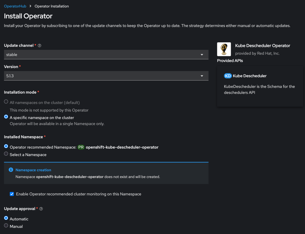
Install and configure Descheduler
First you must install the descheduler tool which performs the dynamic scheduling. RedHat provides a supported form of this using their Kube Descheduler operator, which is available in your cluster in the OperatorHub.
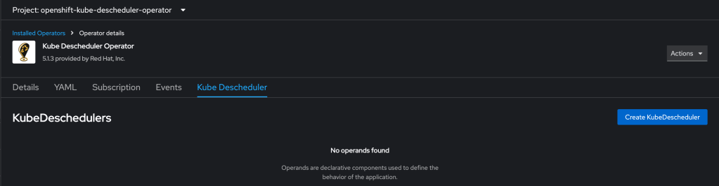
Then you need to create a KubeDescheduler resource describing your rescheduling plan:
Working with the RedHat KubeDescheduler documentation and some failed attempts at experimentation, I crafted the following example definition. Note that currently this leverages two dev keywords that will be folded into the product formally over time.
Many people want to blame AI for significant disruption in the IT job market. I think this is true to a small degree, but it seems to me that it is not sufficient to explain what is going on.
I have personally wanted to blame a growing sort of rapacious value extraction. I think this is true to a moderate degree, and has various contributing factors relating to the watering down of Western Christendom; but I think this is also not sufficient to explain what is going on.
I recently stumbled across this blog post from Sean Goedecke: The good times in tech are over. Taken together with the considerations above, I think this has great explanatory power. Discretionary IT spending is naturally growing far more cautious.
In particular: in the SMB space you already see a pendulum swing away from cloud; consider the notable example of 37signals. Corresponding to this, large enterprises seem to be growing increasingly cautious with IT and cloud expenditure. Famously, for the past two years Hock Tan has insisted that his VMware customer base is largely interested in repatriation of public cloud workloads. This does not mean that cloud has no future whatsoever, but it does mean that some contraction and consolidation lies in the near future for public cloud.