If you are automating activities in VMware Cloud Director—for example, if you are using Terraform to manage your edges and deploy your vApps—you will typically create a Cloud Director API token, which your automation can use to create an authenticated login session with Director for subsequent API calls.
There are interesting complex automation use cases where you might want to create an automation pipeline stretching from the IBM Cloud APIs to the Cloud Director APIs. For example, you might want to use the IBM Cloud APIs to provision a virtual data center (VDC) and then use the Cloud Director APIs—perhaps using Terraform—to deploy a vApp in that VDC. In cases like this, you prefer not to interrupt your automation to create your Cloud Director API token; instead, you want to be able to authenticate with Cloud Director by means of your IBM Cloud API key. Fortunately, that is possible because IBM preconfigures your Director organization with OIDC SSO integration with IBM Cloud IAM.
There are two ways to approach this. Most straightforwardly, if you are a REST API user, you can take the IBM Cloud IAM token that you got in exchange for your IBM Cloud API key, and submit this to Director as an OAuth identity provider token to authenticate a new login session and receive a Director bearer token for that session. You can then use this Director bearer token to make Director API calls for the length of that login session. Alternately, you can further use that Director bearer token to make an API call to create a long-lived Director API token, which you can then provide to tooling like Terraform in order to conduct ongoing management of your VDCs and other Director resources.
I’ve created two sample scripts demonstrating how this works. The first script obtains the Director bearer token and then uses this to call a Director API to list all vApps in each Director instance. Here is an example of its use:
Interestingly, IBM Cloud service IDs are also represented in the Director OIDC SSO. You can create a service ID, and provided you have assigned the service ID sufficient IAM permissions to your VCF as a Service resources, you can use an IAM token generated from the service ID’s API key to authenticate with Director and call Director APIs.
IBM Cloud trusted profiles do not support the creation of API keys. However, trusted profiles are allowed to login to Cloud Director. In order to authenticate your trusted profile with Cloud Director (and possibly to create a Director API token) you will need to extract your trusted profile IAM token by other means than exchange of an API key. If you login to your trusted profile using the ibmcloud CLI (or by means of the IBM Cloud shell), you can extract your IAM token by this means:
scott_test@cloudshell:~$ ibmcloud iam oauth-tokens | grep IAM | cut -d \: -f 2 | sed 's/^ *//'
Bearer eyJraWQiOi. . .aZoC_fZQ
scott_test@cloudshell:~$
My second script uses the alternate approach of leveraging the Director bearer token to create a long-lived Director API token, in this case for each Director instance to which your user has access. Here is an example of its use:
The Director APIs to create these long-lived tokens are not well documented. But essentially what is happening here is that we are creating an OAuth client ID and obtaining the refresh token for that client.
This provider requires that you input the site id for the Director instance of your choice, as well as a pVDC id for the provider VDC (which we sometimes call resource pool) in which you want to create your VDC. The ids for these are not well known.
At the time of this writing, these are the multi-tenant sites and pVDCs available for use:
Site 'IBM VCFaaS Multitenant - SYD', ID 1a4bb41e-f3ce-4b1f-bdb9-b0a77cf83f50, in region au-syd
  pVDC 'SYD04', ID be95acb1-ba8f-466b-b796-22dcd648fd15, in location syd04 supporting provider types: on_demand, reserved
  pVDC 'SYD05', ID 1c4ea91b-fb36-4cd8-9ef7-6fd098db59c7, in location syd05 supporting provider types: on_demand, reserved
Site 'IBM VCFaaS Multitenant - TOR', ID 6352e951-70f6-497f-a80f-94dff58c0734, in region ca-tor
  pVDC 'TOR04', ID de4be466-dfb9-48d4-9d28-657657fef571, in location tor04 supporting provider types: on_demand, reserved
  pVDC 'TOR05', ID 132f3818-0060-4e3e-90db-8b117416fb27, in location tor05 supporting provider types: on_demand, reserved
Site 'IBM VCFaaS Multitenant - FRA', ID 1fff1209-55b8-4667-b737-0e6de5cf5756, in region eu-de
  pVDC 'FRA02', ID f34e7a9f-afb4-430e-86d8-6b1978aebb9c, in location fra02 supporting provider types: on_demand, reserved
  pVDC 'FRA04', ID c66ac0a4-5e52-4b5e-9387-6bb8de7e42b1, in location fra04 supporting provider types: on_demand, reserved
Site 'IBM VCFaaS Multitenant - MAD', ID 8cef7547-3e44-4288-b849-1cd748e7d954, in region eu-es
  pVDC 'MAD02', ID e917160f-54b0-4a01-ac59-f9e23f44e8bd, in location mad02 supporting provider types: on_demand, reserved
Site 'IBM VCFaaS Multitenant - LON', ID f7074684-de9c-42e9-93a5-0358fcb2bf92, in region eu-gb
  pVDC 'LON04', ID 25e910c2-c790-4550-a316-03efa7c29888, in location lon04 supporting provider types: on_demand, reserved
  pVDC 'LON06', ID a24bbff9-8c79-44ab-8bb1-7699f304a1d1, in location lon06 supporting provider types: on_demand, reserved
Site 'IBM VCFaaS Multitenant - TOK', ID 3dca2ae4-fdea-4791-8092-0c879daa2097, in region jp-tok
  pVDC 'TOK02', ID 029c7ff7-da97-48ea-8ed9-0b86c2918f82, in location tok02 supporting provider types: on_demand, reserved
  pVDC 'TOK04', ID 08b78261-d4c9-41e9-baa9-421b493385f7, in location tok04 supporting provider types: on_demand, reserved
Site 'IBM VCFaaS Multitenant - WDC', ID 25fb5553-72a6-49ca-85b8-f18086cbac0b, in region us-east
  pVDC 'WDC06', ID 595d7f76-b1b2-429f-bb67-e357befa9da7, in location wdc06 supporting provider types: on_demand, reserved
  pVDC 'WDC07', ID efc17eff-fb3e-4b56-8252-44657738c539, in location wdc07 supporting provider types: on_demand, reserved
  pVDC 'WDC04-WDC07', ID 9a46dcce-84d1-4fca-a929-42bc2174ffba, in location wdc04 supporting provider types: on_demand, reserved
Site 'IBM VCFaaS Multitenant - DAL', ID 40e701cd-ef86-4d5e-a847-e7c336f11f27, in region us-south
  pVDC 'DAL10', ID f864f016-2c34-4658-95e7-dd3363408d76, in location dal10 supporting provider types: on_demand, reserved
  pVDC 'DAL13', ID 1df84086-b3af-481e-a535-e3554b809aed, in location dal13 supporting provider types: on_demand, reserved
  pVDC 'DAL12', ID 5b4af31c-383b-422b-b297-0ea6ed8af479, in location dal12 supporting provider types: on_demand, reserved
In 2024, Broadcom simplified VMware product pricing and packaging. The VMware Cloud Foundation (VCF) offering now encompasses a wide variety of VMware software and features, with a relatively smaller number of software and features being sold as add-ons. As part of this simplification, Broadcom required all customers and cloud providers to make new commitments and to create new license keys.
Cloud providers are uniquely entitled for on-demand licensing of VMware products beyond their contract commitment. In exchange for this benefit, Broadcom expects that the vCloud Usage Meter product “must be used” to monitor and report usage of VMware products. IBM secured an extension of this requirement so that we could update our automation and develop integration points for our customers. IBM has now released updated VMware license keys and Usage Meter support, and IBM’s customers are expected by Broadcom—and therefore by IBM—to “immediately” install these in order to remain entitled to VMware software. . . . read more at Updates to VMware license keys and the use of vCloud Usage Meter in IBM Cloud
Broadcom/VMware reappointed me as a VMware vExpert for a fifth year. The vExpert program recognizes VMware experts for exceptional community involvement and giveback.
IBM used to have quite a few vExperts, but many of them departed with the separation of Kyndryl. As far as I can tell, Mike Nelson and I are IBM’s only vExperts at present. Congratulations, Mike!
I’ve expanded my sample IBM Cloud for VMware Solutions API usage to demonstrate how you can remove NFS storage, hosts, clusters, and VCS instances dynamically.
I’ve expanded my sample IBM Cloud for VMware Solutions API calls to demonstrate how you can add file storage dynamically to clusters in your vCenter Server (VCS) instance.
It’s been awhile since I first posted sample IBM Cloud for VMware Solutions API calls. Since then, our offering has moved from NSX–V to NSX–T, and to vSphere 7.0. This results in some changes to the structure of the API calls you need to make for ordering instances, clusters, and hosts.
VMware Solutions instances in IBM Cloud are deployed with a built-in Active Directory domain with one or two directory controllers. Recently IBM Cloud changed the domain name requirements to require three qualifiers (e.g., cloud.example.com) rather than two (e.g., example.com). The reason for this is that we want to ensure you can integrate with your existing domain and forest without experiencing conflict. The domain controllers are configured as SSO provider for vCenter and NSX, and also as DNS provider for the infrastructure components. IBM Cloud creates an administrator userid in this domain which it uses for subsequent operations, such as logging into vCenter to add a new host, updating DNS records for that host, and creating utility accounts for add-on services like Veeam.
This Active Directory domain is your responsibility to secure and manage, including backup, patching, group policy, etc.
In order of integration from loosest to tightest coupling:
1. No integration
You are free to leverage your instance domain directly for user management within the instance. You can point additional components to the instance’s domain controllers for SSO; for example, the IBM Cloud automation does this for you when it deploys and configures HyTrust Cloud Control. You can join other devices to the domain and also use this for DNS management beyond the instance infrastructure.
2. Additional SSO provider
This option and all of the following options each entail some kind of integration with your instance and your existing Active Directory forest. You will first need to establish network connectivity between your instance and your existing Active Directory forest. You might accomplish this with either a VPN connection or a direct link between IBM Cloud and your on-premises environment. As always, you should take great care to secure your domain controllers, so you should explore security measures such as the use of read-only directory controllers, session recording, bastion servers, and gateway firewalls.
You can leverage your own Active Directory domain for SSO purposes by configuring your directory controllers as additional SSO providers for vCenter and NSX manager and by granting your users and groups appropriate permissions. You will need to determine how you configure DNS; some customers manually duplicate the DNS records from their instance domain into their existing Active Directory domain, but it is also possible to establish mutual DNS delegation between the two Active Directory domains.
This approach may allow you to limit the cloud connections to your directory controllers so that you are only opening up LDAPS and DNS ports.
3. One-way trust
You can establish one-way trust from your instance’s Active Directory domain controllers to your existing Active Directory domain. This will enable you to expose and authorize your existing users and groups to vCenter and NSX manager without having to add these directly as SSO providers. You may need to make additional provision for DNS updates, either copying them to your existing domain or establishing DNS delegation to the instance’s domain.
4. Two-way trust
This option requires your existing domain to establish mutual trust with your instance’s domain. If you are comfortable doing this, it could simplify your DNS management between the two domains.
5. Forest merge
I am not aware of any IBM Cloud customers who have done this, and I do not recommend it since it is a disruptive and potentially risky operation. The idea here is to merge the instance’s forest with your existing forest and to configure the instance’s domain as a child domain of your existing domain.
6. Rebuild
IBM Cloud’s VMware Solutions Shared offering implements a variation of the forest merge. It deploys VCS instances and builds VMware Cloud Director environments on top of them. This solution leverages an existing internal Active Directory forest and domain. After each new VCS instance is deployed, our process removes the VCS instance from its domain and reconfigures it to point to the existing domain.
A variation of this option is to create a new child domain in your existing forest for your VCS instance, and leverage the controllers for this child domain for use with your VCS instance.
There are a few important points to observe:
You should either deploy your instance with the same domain name that you intend to convert it to, or else you should accept the fact that your infrastructure components will have host names in a different DNS domain from your Active Directory domain. Changing the DNS domain of infrastructure components is not supported by IBM Cloud automation.
You will need to re-create the IBM Cloud automation user in your existing domain as an administrator and ensure that this user has administrative permissions in vCenter and NSX manager. This user may in the future create additional users or DNS entries. After performing the reconfiguration, you should open a support ticket to the VMware Solutions team asking them to update the automation user’s password in the IBM Cloud database for your instance, and provide the updated password.
Because this process is complex it is error prone, and you should consider this option only if the options above do not work for you. Additionally, you should practice this with a non-production or pre-production VCS deployment, including the test of adding a new host to the environment, before you implement it in production.
Happy birthday to VMware Solutions on IBM Cloud! Five years ago today our first release became generally available. Five years later, we’re still working hard to give you the best enterprise VMware on cloud.
IBM Cloud offers IBM–managed VMware Cloud Director through its VMware Solutions Shared offering. This offering is currently available in IBM Cloud’s Dallas and Frankfurt multi-zone regions, enabling you to deploy VMware virtual machines across three availability zones in those regions.
IBM Cloud also offers a virtual private cloud (VPC) for deployment of virtual machine and container workloads. Although VMware Cloud Director is operated in IBM Cloud’s “classic infrastructure,” it is still possible to interconnect your Cloud Director workload with your VPC workload using private network endpoints (PNEs) that are visible to your VPC.
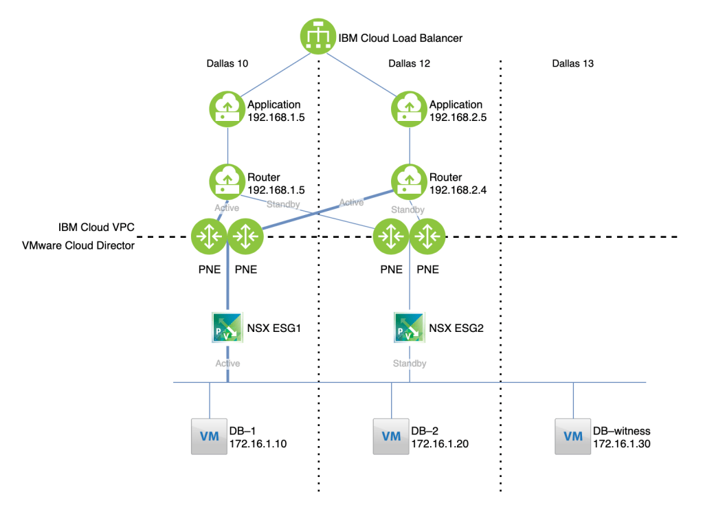
In this article we’ll discuss how to implement this solution. This solution allows for bidirectional connectivity, but for illustrative purposes consider the use case of hosting an application in IBM Cloud VPC and a database in VMware Cloud Director:
The load balancer distributes connections to applications running on virtual server instances (VSIs) in our example, or optionally to kubernetes services. The application is deployed in two zones for high availability.
Each zone in the VPC has a router that will tunnel traffic to and from Cloud Director using BGP over IPsec. For the purposes of this exercise we used a RedHat Enterprise Linux 8 VSI, but you could deploy virtual gateway appliances from a vendor of your choice.
The VPC routers connect over the private IBM Cloud network through private network endpoints (PNEs) to edge appliances in Cloud Director.
The Cloud Director workload is distributed across three virtual datacenters (VDCs), one in each availability zone. Two edge services gateways (ESGs), one in each of two zones, serve as the ingress and egress points. These operate in active–standby state so that a stateful firewall can be used.
The database is deployed across three zones for high availability.
Caveats
The solution described here uses the IBM Cloud private network. This is a nice feature of the solution, but for reasons that may not be initially obvious, it is also required at the moment. If you wish to connect a single availability zone between VCD and VPC, you could do so using a public VPN connection between your VCD edge and the IBM Cloud VPC VPN gateway service. However, the VPC VPN service currently does not support BGP peering, so it is not possible to create a highly available connection that is able to failover to a different VCD edge endpoint.
Also, the solution outlined here deploys only a single router device in each VPC zone. For high availability, you likely want to deploy multiple virtual router appliances, and for routing purposes share a virtual IP address which you reserve in your VPC subnet. At this time, IBM Cloud VPC does not support multicast or protocols other than ICMP, TCP, and UDP. These limitations exclude protocols like HSRP and VRRP; you should ensure that your router’s approach to HA is able to operate using unicast ICMP, TCP, or UDP.
Deploy your VPC resources
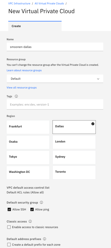
Create a VPC in Dallas or Frankfurt. The VPC will automatically generate address prefixes and subnets for you; I recommend you de-select “Create a default prefix for each zone” so that you can choose your own later:
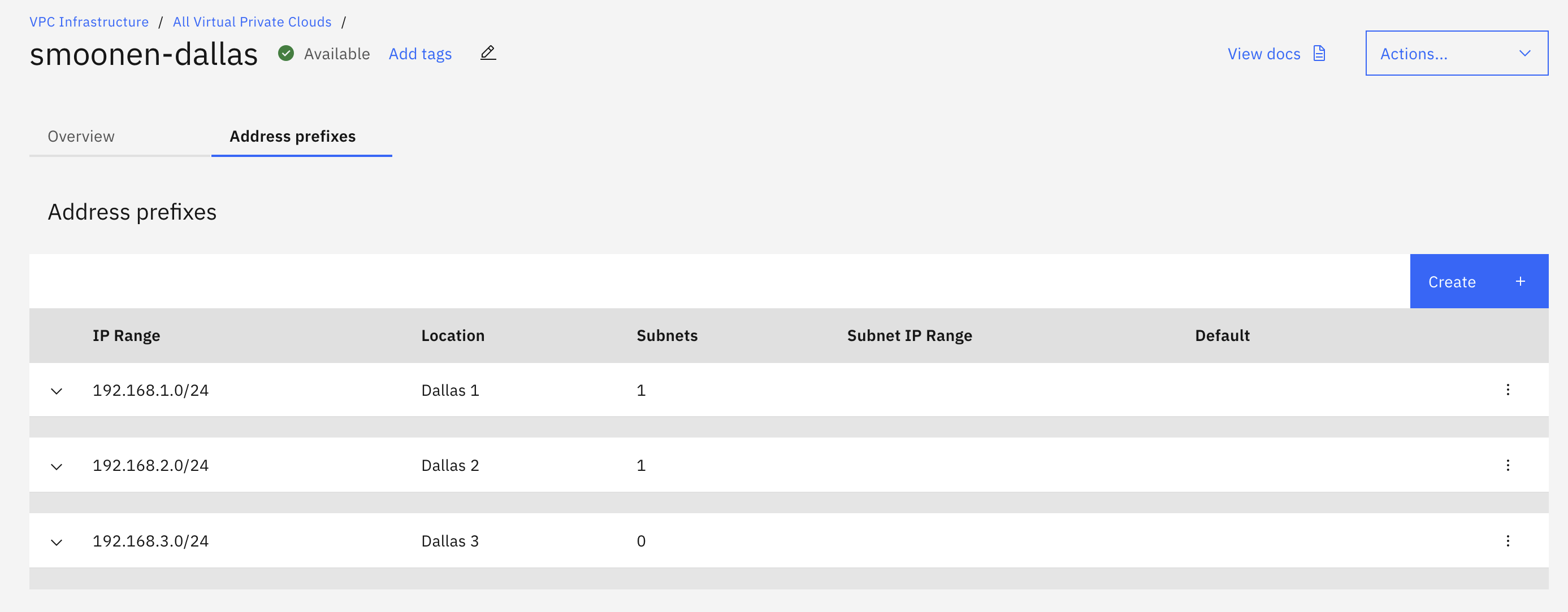
Next, navigate to your VPC and create address prefixes of your choice:
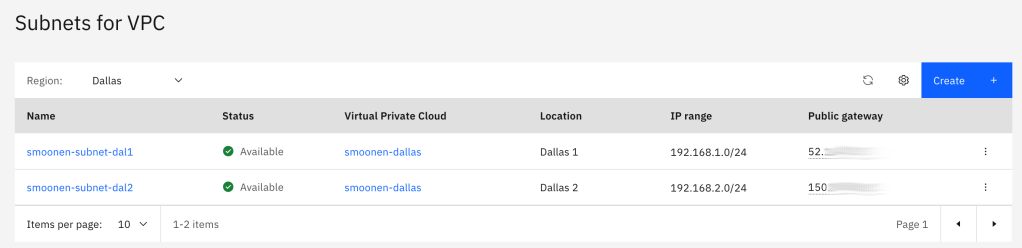
In order to create subnets, you must navigate away from the VPC to the subnet page. In our case, since we are hosting workloads in only two zones, we had a need only for two subnets:
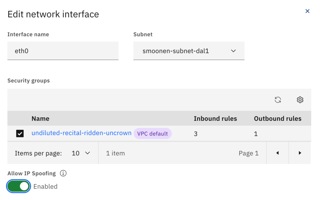
Next, create four virtual server instances (VSIs), two in each zone. Within each zone, one VSI will serve as the application and the other will serve as a virtual router. For the purposes of this example we use RedHat Enterprise Linux 8.
You need to modify the router VSI network interfaces, either when you create it or afterwards, to enable IP spoofing. This will allow the routers to route traffic other than their own IP address:
Be sure to update the operating system packages and reboot each VSI.
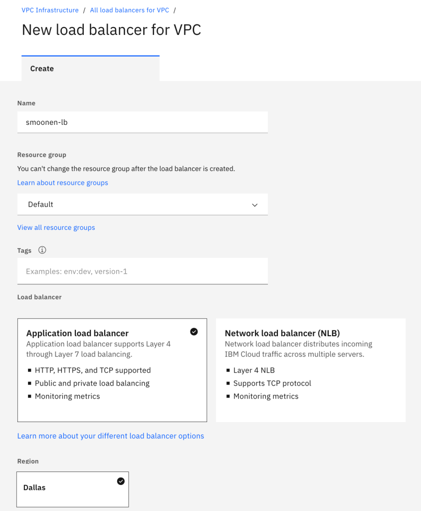
Finally, create an IBM Cloud load balancer instance pointing to each of your application VSIs. Because this is a multi-zone load balancer you must use the DNS-based application load balancer:
Deploy your Cloud Director resources
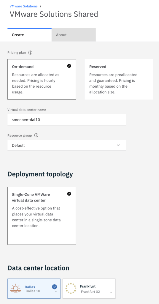
Next create three VMware Solutions Shared virtual data centers (VDCs). Note that while VPC availability zones are named 1, 2, and 3, VDC availability zones are named according to the IBM Cloud classic infrastructure data center names. Thus, we will deploy to Dallas 10, 12, and 13, which correspond to the three VDC zones:
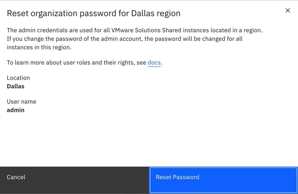
After creating your three virtual data centers, you need to view any one of these VDCs and reset the administrator password to gain access to the single Cloud Director organization for your account. Using this administrator account you can create additional users and optionally integrate with your own SSO provider:
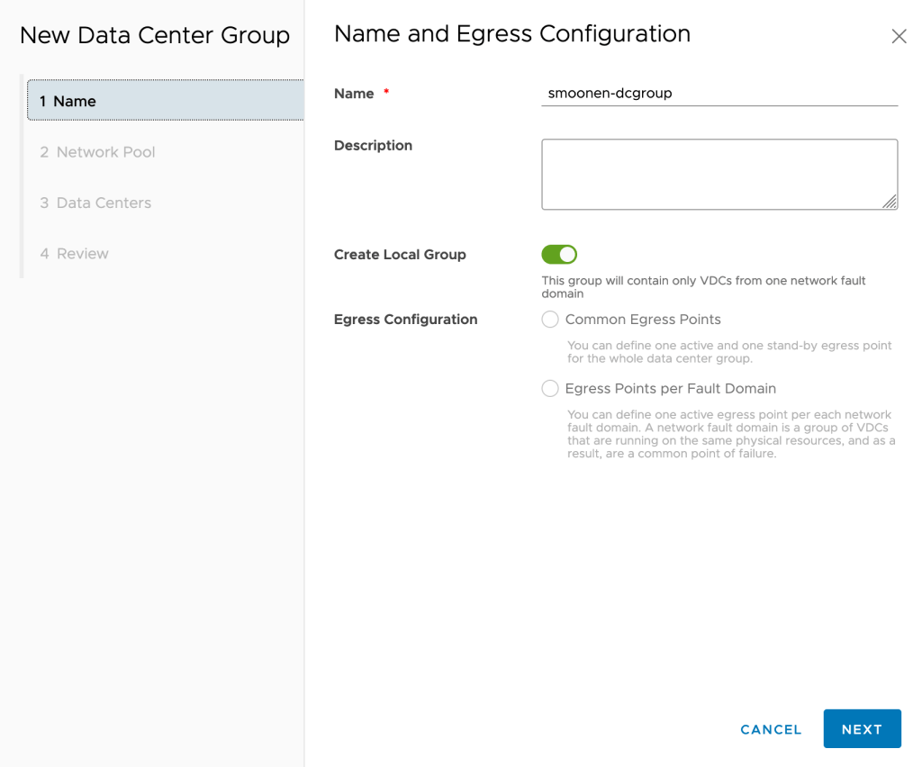
Next, use these credentials to login to the Cloud Director console. We will create a Data Center Group and assign all three of our VDCs to it so that they have a shared stretch network and network egress. Navigate to Data Centers | Data Center Groups and create a new data center group. Ensure that you select the “Create Local Group” option; although the VDCs are actually in different availability zones, they are designated in the same fault domain from a Cloud Director perspective and we will use active-standby routing. There is only one network pool available for you to use:
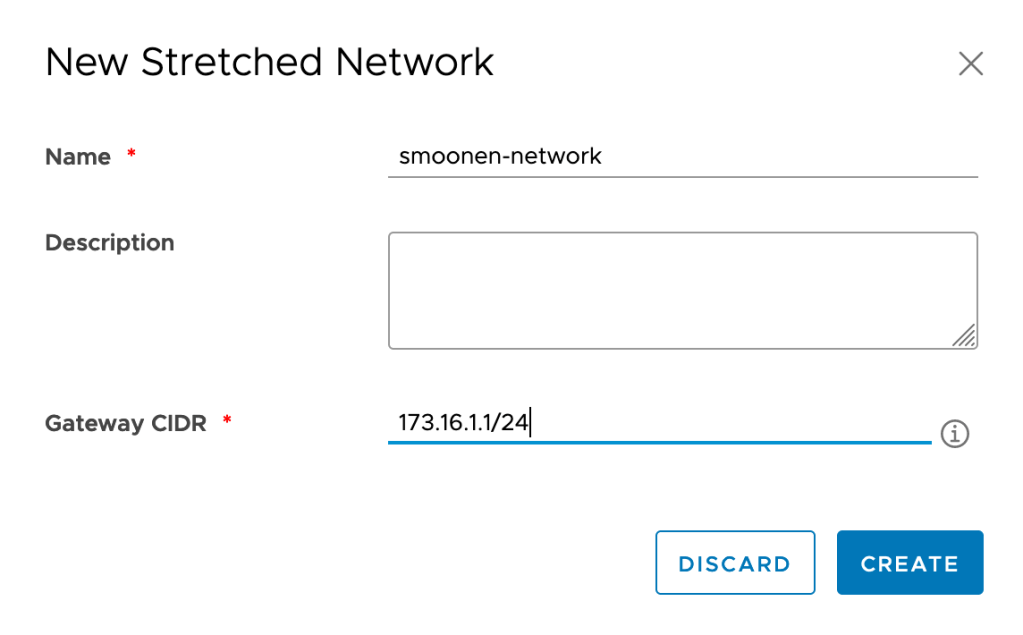
After creating the data center group, create a stretched network that will be shared by all three VDCs:
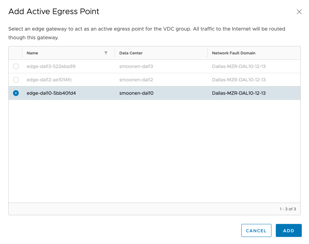
Add your DAL10 edge as the active egress point, and your DAL12 edge as the passive egress point:
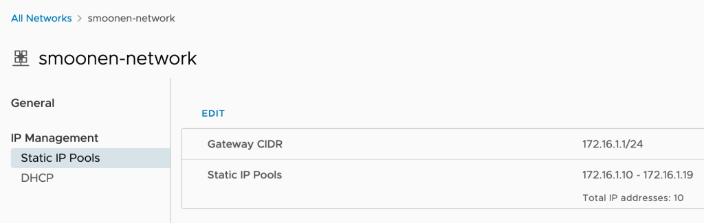
Next, navigate to each of your VDCs, view the stretched network, and create an IP pool for each VDC that is a subset of your stretched network:
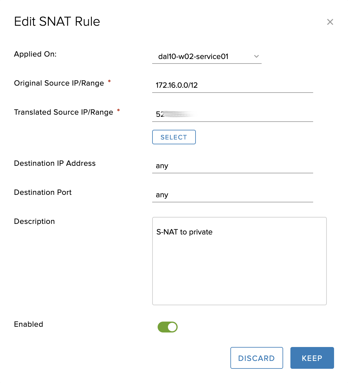
Next, configure your DAL10 and DAL12 edges (see IBM Cloud docs for details) to allow and to SNAT egress traffic from your VPC to the IBM Cloud service network (e.g., for DNS and RedHat Satellite) and to the public network. If you wish to DNAT traffic from the public internet to reach your virtual machines, keep in mind that the DAL10 edge is the active edge and you should not use DAL12 for ingress except in case of DAL10 failure.
Minimally you want your workload to reach the IBM private service network which includes 52.117.132.0/24 and 161.26.0.0/16. Because we are using private network endpoints (PNEs) you also need to permit 166.9.0.0/15; this address range is also used by any other IBM Cloud services offering private endpoints. For this example I simply configured the edge firewalls to permit all outbound traffic to both private and public:
You must configure an SNAT rule for the private service network (note that this rule is created on the service interface):
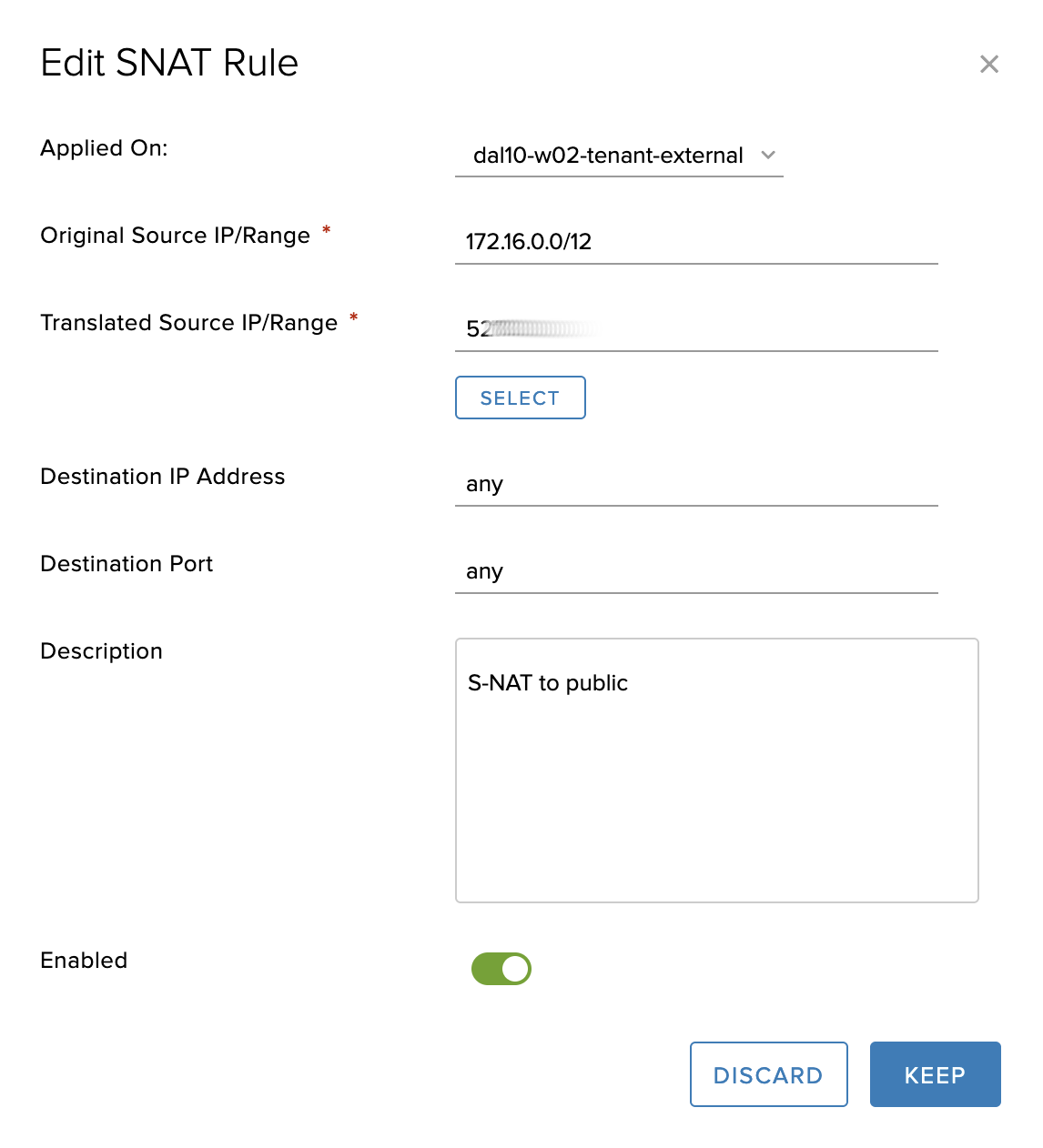
and, if needed, an SNAT rule for the public network (note that this rule is created on the external interface):
Next, create the virtual machines that will serve as your database, one in each VDC. For the purposes of this example, we deployed RHEL 8 virtual machines from the provided templates and connected them to IBM Cloud’s Satellite server following the directions in the /etc/motd file. There are a few caveats to the deployment:
You should connect the virtual machine interfaces to the stretched network before starting them so that the network customization configures their IP address. Choose an IP address from the pool you created earlier.
At first power-on, you should “power on and force recustomization;” afterwards you can view the root password from the customization properties.
When using a stretched network, customization does not set the DNS settings for your virtual machines. For RHEL we entered the IBM Cloud DNS servers into /etc/sysconfig/network-scripts/ifcfg-ens192 as follows:
DNS1=161.26.0.10
DNS2=161.26.0.11
Configure BGP over IPsec connectivity between VCD and VPC
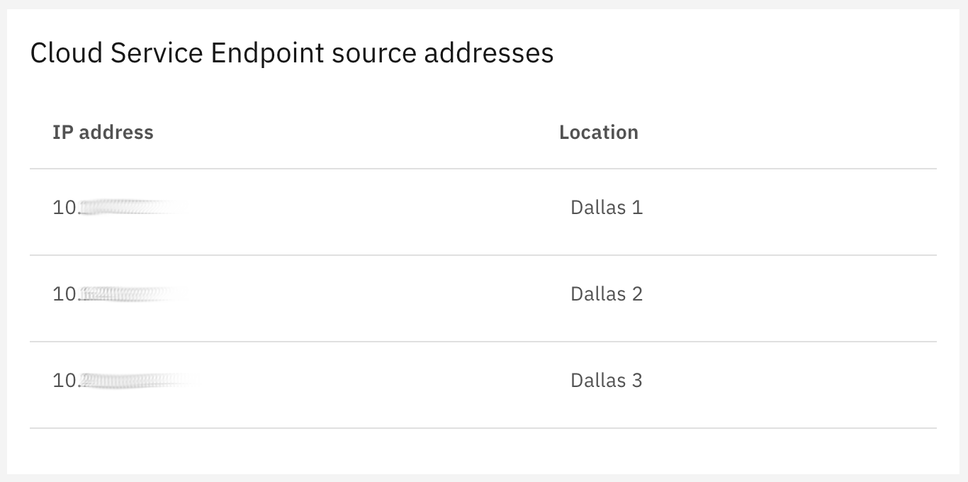
In order to expose your Cloud Director edges to your VPC using the IBM Cloud private network, you must create private network endpoints (PNEs) for your DAL10 and DAL12 VDCs. First, in the IBM Cloud console, view your VPC details. A panel on that page lists the “Cloud Service Endpoint service addresses” which are addresses not visible to your VPC but which are the addresses representing your VPC that you will need to permit to access your PNEs. Take note of these addresses:
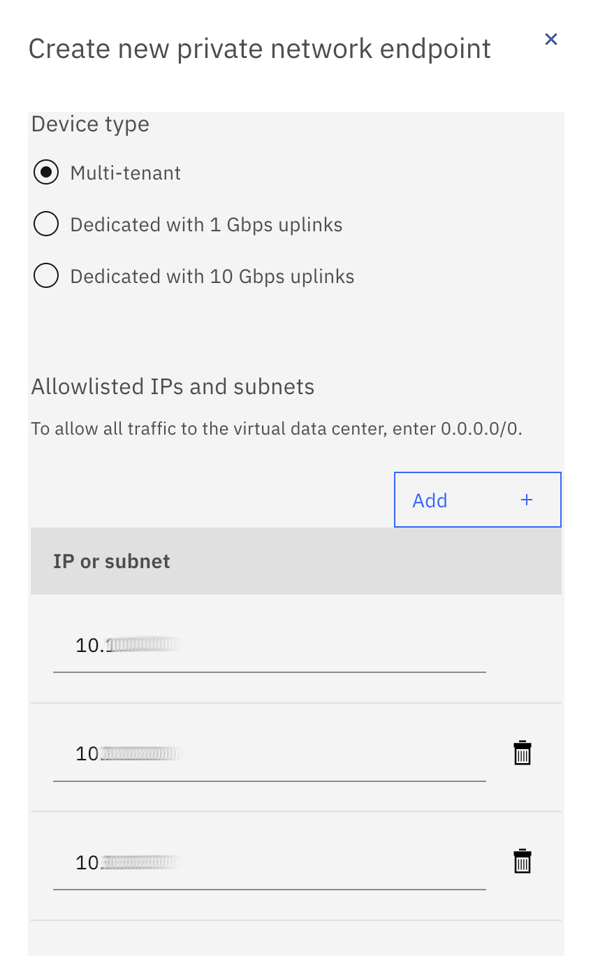
Now, navigate to your DAL10 and DAL12 VDCs in the IBM Cloud console and click “Create a private network endpoint.” Select the device type of your choice and enter the IP addresses you noted above:
The PNE may take some time to create as it is an operator assisted activity. After it has been successfully created, you will need to create a second PNE in each of the two zones. The reason we need to create a second PNE is that the PNE hides the source IP address of incoming connections, so we cannot configure policies for two different IPsec tunnels using the same PNE. The IBM Cloud console does not allow you to create a second PNE automatically, so you must open a support ticket to the VMware Solutions team. Phrase your ticket as follows:
Hi, I have already created a PNE for my VCD edges edge-dal10-xxxxxxxx and edge-dal12-yyyyyyyy. Please create a second service IP for each of these edges with an additional PNE for each edge. Please use the same whitelist for the existing PNEs. Thank you!
Note that in our example we are connecting only Dallas 1 and Dallas 2 zones from our VPC to Cloud Director. If you wanted to connect Dallas 3 as well, you would need to request three rather than two PNEs for each of your DAL10 and DAL12 edges.
Now we need to configure each of our two NSX edges and our two VPC routers to have dual BGP over IPsec connections to their peers. You need to select which PNE will be used for each VPC router connection.
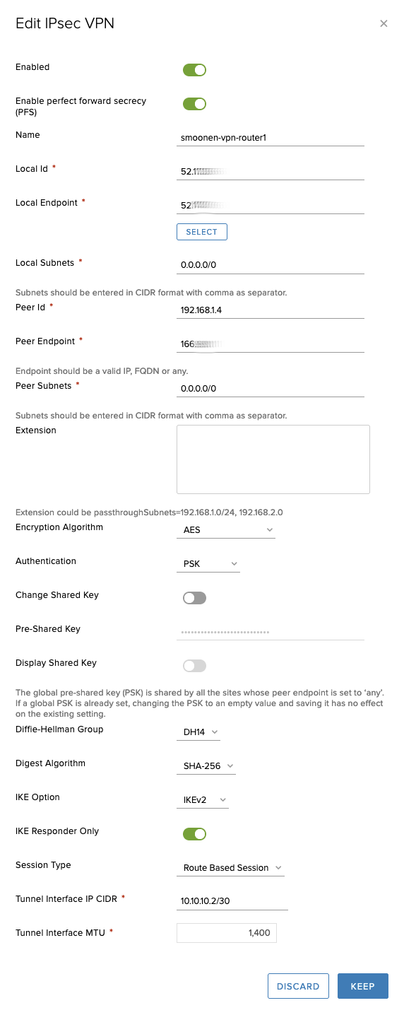
On the VCD side, the IPsec VPN site configuration for one of the VPC routers looks as follows. In this case, the 52.x address is the PNE’s “service network IP” and the 166.x address is the PNE’s “private network IP:”
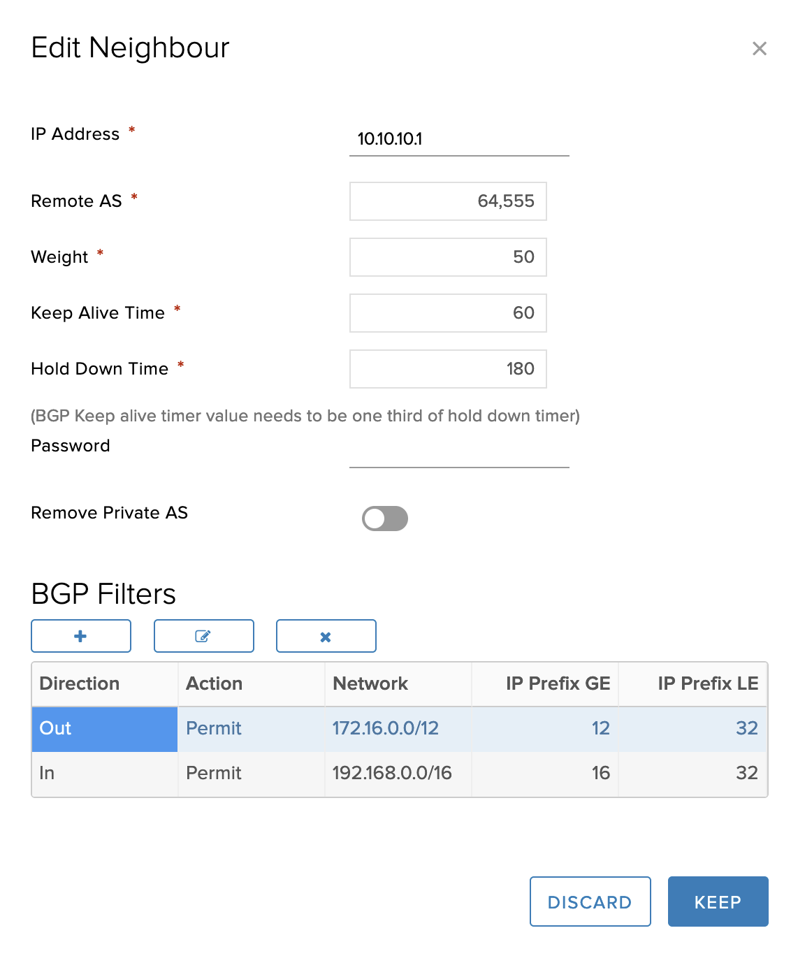
And the corresponding BGP configuration is as follows:
Finally, you must be sure to permit the VCD and VPC interconnectivity in both edge firewalls:
For the purposes of this example we are using RHEL8 VSIs as simple routers on the VPC side. First of all, we need to modify /etc/sysctl.conf to allow IP forwarding:
Next we installed the libreswan package for IKE/IPsec support, and the frr package for BGP support.
In order to use dynamic routing, the IPsec tunnel must be configured using a virtual tunnel interface (VTI). The IPsec configuration for our Dallas 1 router is as follows. The left and leftid values are the address and identity of the router appliance itself. The right value has been obscured; it reflects the address of the VCD edge as known to the router; this is the PNE’s “private network IP.” The rightid value has also been obscured; it reflects the identity of the VCD edge, which we have previously set to the PNE’s “service network IP:”
Note that the tunnels use a different mark and VTI interface. Next, in /etc/frr/daemons, enable bgpd:
bgpd=yes
Then define your tunnel interfaces in /etc/frr/zebra.conf; these are the interfaces for our Dallas 1 router:
!
interface vti1
ip address 10.10.10.1/30
ipv6 nd suppress-ra
!
interface vti2
ip address 10.10.10.5/30
ipv6 nd suppress-ra
Finally, configure BGP in /etc/frr/bgpd.conf:
hostname smoonen-router1
router bgp 64555
 bgp router-id 10.10.10.1
  network 10.10.10.0/30
  network 10.10.10.4/30
  network 192.168.1.0/24
  neighbor 10.10.10.2 remote-as 65010
  neighbor 10.10.10.2 route-map RMAP-IN in
  neighbor 10.10.10.2 route-map RMAP-OUT out
  neighbor 10.10.10.2 soft-reconfiguration inbound
  neighbor 10.10.10.2 weight 2
  neighbor 10.10.10.6 remote-as 65010
  neighbor 10.10.10.6 route-map RMAP-IN in
  neighbor 10.10.10.6 route-map RMAP-OUT out
  neighbor 10.10.10.6 soft-reconfiguration inbound
  neighbor 10.10.10.6 weight 1

ip prefix-list PRFX-VCD seq 5 permit 172.16.0.0/12 le 32
ip prefix-list PRFX-VPC seq 5 permit 192.168.0.0/16 le 32

route-map RMAP-IN permit 10
 match ip address prefix-list PRFX-VCD
route-map RMAP-OUT permit 10
 match ip address prefix-list PRFX-VPC

log file /var/log/frr/bgpd.log debug
Taken together, we have configured:
Cloud Director to use DAL10 as active and DAL12 as standby
Cloud Director edges will advertise the entire stretch network (172.16.1.0/24) to the VPC routers
Each VPC router is configured to prefer the DAL10 edge
Each VPC router will advertise its own zone (192.168.1.0/24 or 192.168.2.0/24) to the Cloud Director edges
Now enable IPsec and FRR:
systemctl start ipsec
systemctl enable ipsec
ipsec auto --add routed-vpn-esg1
ipsec auto --add routed-vpn-esg2
ipsec auto --up routed-vpn-esg1
ipsec auto --up routed-vpn-esg2

chown frr:frr /etc/frr/bgpd.conf
chown frr:frr /etc/frr/staticd.conf
systemctl start frr
systemctl enable frr
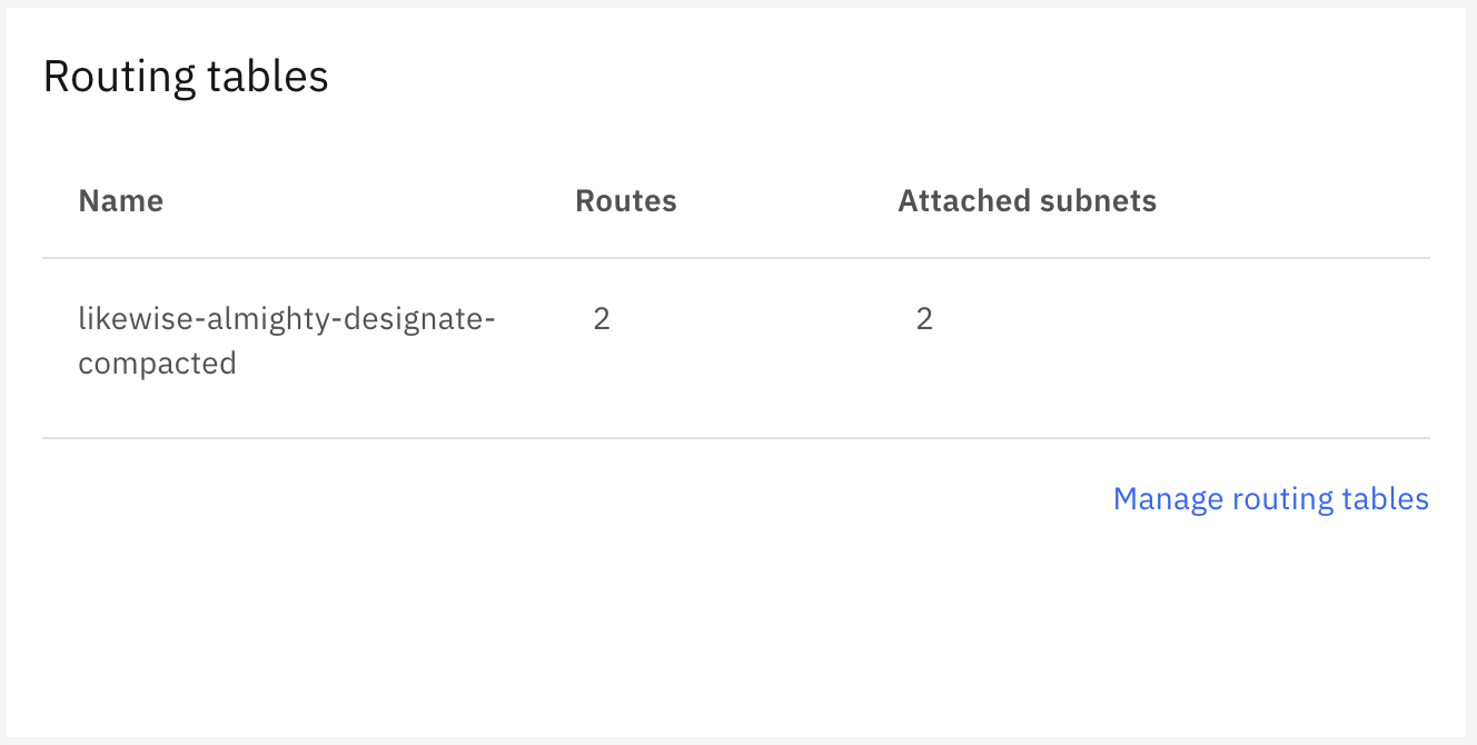
Finally, you need to visit the IBM Cloud console and find the route table configuration for your VPC:
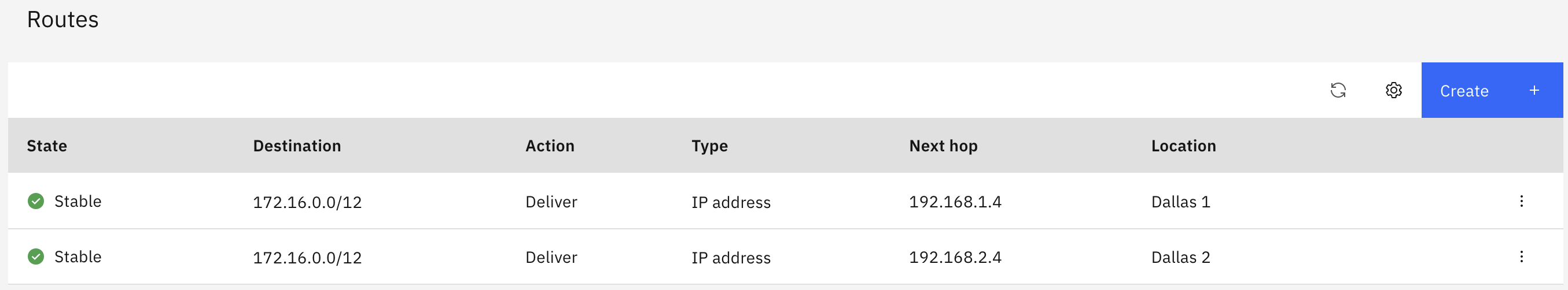
Modify the route table configuration to direct the VCD networks to your router VSI in each zone. Remember that for this example we are hosting applications only in two zones:
After the tunnel is up and the initial BGP exchange complete, you should have bidirectional connectivity between both environments. Here is a ping from one of our application VSIs:
[root@smoonen-application1 ~]# ping -c 3 -I 192.168.1.5 172.16.1.10
PING 172.16.1.10 (172.16.1.10) from 192.168.1.5 : 56(84) bytes of data.
64 bytes from 172.16.1.10: icmp_seq=1 ttl=61 time=3.21 ms
64 bytes from 172.16.1.10: icmp_seq=2 ttl=61 time=2.34 ms
64 bytes from 172.16.1.10: icmp_seq=3 ttl=61 time=2.87 ms

--- 172.16.1.10 ping statistics ---
3 packets transmitted, 3 received, 0% packet loss, time 2003ms
rtt min/avg/max/mdev = 2.344/2.809/3.210/0.356 ms
[root@smoonen-application1 ~]#
We have not tuned BGP, but in spite of this, if we disable BGP on the DAL10 edge (this effectively severs both its connection to the stretched network and its connection to VPC), we see that the connectivity from the VPC fails over to the DAL12 edge:
64 bytes from 172.16.1.10: icmp_seq=16 ttl=61 time=2.51 ms
64 bytes from 172.16.1.10: icmp_seq=17 ttl=61 time=16.9 ms
64 bytes from 172.16.1.10: icmp_seq=18 ttl=61 time=2.63 ms
64 bytes from 172.16.1.10: icmp_seq=137 ttl=61 time=8.52 ms
64 bytes from 172.16.1.10: icmp_seq=138 ttl=61 time=6.06 ms
64 bytes from 172.16.1.10: icmp_seq=139 ttl=61 time=5.07 ms
Conclusion
We have successfully established bidirectional connectivity over the IBM Cloud private network between VMware Cloud Director and IBM Cloud VPC using BGP over IPsec.
As described above, it is possible to extend this solution by deploying a router appliance in the third VPC availability zone, in which case you would need to deploy two more PNEs, one for each of your VCD edges. Also, you will need additional PNEs if you deploy more than one router appliance into each zone for HA. Thus, you could require up to twelve PNEs (two router appliances in each of three zones, each of which has a connection to two VCD edges).
Many thanks to Mike Wiles and Jim Robbins for their assistance in developing this solution.